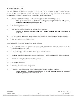
6.3.2
POWER LEVEL AND FREQUENCY CONTROL LOGIC
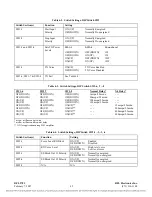
Switches SW1-3 and SW1-4 determine the power level used to transmit a BLOCK if the SEND signal
is active. The power level can be programmed for 1W, 3W, or 10W. The power level is always set for
3W whenever SEND is not active. This will guarantee a 3W level when voice is active. The power
output signals are A-SWITCH and B-SWITCH. These are located at edge connector pins A14 and
B14 respectively.
As this is not a frequency-shift-keying system, the OSC1-2 at edge connector pin A13 is held to a
logic-high and OSC-3 at edge connector pin B13 is held to a logic-low. Therefore, the transmit
frequency is always programmed with the “Center Frequency” rotary switches on the transmitter
module. The “Shift Up” and “Shift Down” rotary switches are not used.
6.3.3
LOCAL CARRIER AND TRANSMIT VOICE CONTROL LOGIC
Local carrier is active when either a logic-high is applied to the VOICE-REQUEST input at edge
connector pin A16 (indicating that voice is active), or when SEND is active and STOP is not active.
The CARRIER-SWITCH signal at edge connector pin C15 will be a logic-high when the local carrier
is active.
Voice is enabled by switch SW1-5 if the voice option is installed. Voice will only be transmitted when
SEND is not active. The AM-ENABLE signal at edge connector pin B24 will be a logic-high when
voice is being modulated over the carrier frequency.
6.3.4
TRANSMITTER FAIL CIRCUIT
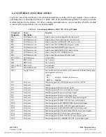
The Transmitter Fail Circuit can be configured by switches SW1-6, SW1-7 and SW1-8 for 3ms, 50ms,
100ms or 150ms alarm pickup delay. The CARRIER-DETECT input applied to edge connector pin
C13 must be a logic low within the allotted time after SEND initially goes to a logic low. If it does
not, TX FAIL LED DS8 will light and TX FAIL alarm relay will de-energize, indicating a power
amplifier failure. The condition will be logged by the sequence of events module (SOE).
When the CARRIER-DETECT input is a logic low, DS3 will be lit.
6.3.5
BLOCK CONTROL LOGIC
The receiver detector monitors the receive carrier signal strength, and generates a logic signal which is
applied to edge connector pin A29 (SIG-COMP-IN) of the 9785 AM Logic Module. A logic-high
SIG-COMP-IN or a logic-high CARRIER-SWITCH (indicating local carrier is active) will generate a
block. The local carrier blocking function can be disabled with switch SW2-1 if desired. A block
received from the local carrier will be held for an additional 3 ms after blocking inputs go inactive. A
block received from the remote carrier is not held. DS1 will light when SIG-COMP-IN is active. This
indicates that a received signal is detected.
RFL 9785
RFL Electronics Inc.
February 7, 2007
6-3
(973) 334-3100

