Section 2.
GENERAL INFORMATION
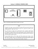
Figure 2-1. RFL 9785 Programmable ON/OFF Powerline Carrier System
NOTE
Throughout this manual, specific terminal block terminals, DIP switch sections, and IC pin
numbers are noted by the circuit symbol number followed by a dash and the terminal, section,
or pin number (TB1-1, SW1-1, IC1-1, etc).
The circuit boards in the RFL 9785 use DIN 41612 Type C connectors which contain
columns of 32 pins. All modules have pins in columns A and C and provide a total of 64 pins
per connector. In addition to this, the AM Logic Module has pins in column B giving an
additional 32 pins for a total of 96 pins. Note that the pins extend from the front to the back of
the unit into the I/O Module connector.
The I/O connector pins are a mirror image of the front connector pins. In order to clarify
signal flow, the signal on pin 1 of a front module goes directly through the mother board to
pin 1 of the rear module, as marked on the rear module circuit board. Note, however, that this
may not be marked as pin 1 on the housing of the rear module’s connector.
POWER
RFL 9785
Programmable ON/OFF
Powerline Carrier System
RFL Electronics Inc.
SOE
RS-232
RECEIVE
dB
RX DETECT
BLOCK OUT
START INPUT
STOP INPUT
RESERVE INPUT
REMOTE INITIATE
TX CARRIER ON
TX FAIL
RFL 9785
RFL Electronics Inc.
June 18, 2009
2-1
(973) 334-3100

