RFL 9785
RFL Electronics Inc
.
March 1, 2013
22-
3
(973) 334-3100
5)
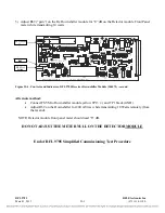
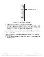
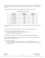
Adjust R69 (“gain”) on the Rx Downshifter module for “0” dB on the Detector module Front Panel
meter while transmitting 10 watts.
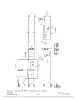
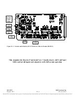
Figure 22-4. Controls and Indicators, RFL 9785 Receiver Downshifter Module (106575) - second
Alternate method:
•
Connect FSVM to Downshifter module yellow TP13 (+) and TP1 black (GND).
•
Adjust R69 on the Downshifter for 200 mVrms while transmitting 10 Watts remotely (from
the far end).
NOTE: Detector module front panel meter should read “0” dB.
DO NOT ADJUST THE METER NULL ON THE DETECTOR MODULE
End of RFL 9785 Simplified Commissioning Test Procedure
C
8
P
TP1
U
R
5
TP1
TP1
R
5
TP1
C9
C
8
R5
R
5
C
9
C
7
L
U1
C
8
R
5
R
5
R6
R2
C
3
C
6
U1
C8
TP1
R
4
L
1
Y
CR
CR
C
C
2
U1
Y
C
7
C
7
C
9
C7
C
3
CR
C8
TP1
TP1
TP
TP
TP
TP
TP
R
1
R1
U
U
TP
TP
R
4
R
4
R4
R4
R4
R
4
R
3
R
3
R
3
R
3
R
3
R
3
R
3
R
3
R
3
R
2
R
3
R
2
R
2
R
2
R
2
R
2
R
2
R
1
R
1
R
2
R
2
R
1
R
1
R
1
R
1
R
1
R
1
R
R
R
R
R
R
R
R
R
R
4
L
L
L
L
L
C
C7
TP1
C
3
C
3
C
3
C
5
C2
C2
C
8
C7
C
7
R5
C
6
C
6
C5
C5
C6
C
6
C
8
C
5
C6
C6
C
5
C
6
C4
C4
C4
C4
C5
C5
C4
C
5
C5
C4
C
5
C
4
C
3
C
3
R6
C
1
C
2
C
C1
C1
C1
C1
C1
C1
C
L
1
C
7
C
6
C
4
C
4
C
4
C
3
C3
C
2
C
2
C
2
C
1
C1
C C
C
C
TP1
J
U1
U
C
6
R6
Q
U
C
3
CR
C
2
U
SW
U
TP
TP
R6
FL10
U
C
8
R
4
C
9
R4
C
9
L
L
C2
C
1
C
C
9
C
8
C
8
C
2
L
U1
R5
R5
R5
J1
U
C9
C
9
C
1
C
1
C
1
C
1
C9
J2
R6
R6
R6
R
7
U1
R6
13
TP2
R6
C
9
C
1
C
1
C7
TP1
9785 RX DOWNSHIFTER ECB NO
G
AI
GAI
L
HI
5
4
3
2
1
ATTE
d
0
1999
RFL
ELECTRONICS
INC.,
.2 .5 1 2 4 8 1 3 6 1
2
2
5
5
1
KH
32
A
C
1
+
+
+
+
+
+
+
+
+
1
+
+
.5W
47.5
MV2
7.
1
5
3
5-
2
R69
TP1 (COM)
Black
TP13 (+)
Yellow

