


Section 7.
TRANSMITTER MODULE
U1
C13
C9
C8
P1
R3
C19
U2
DS1
J1
C18
C3
C16
C27
C30
U6
U3
R23
J2
TP1
L1
U4
CR1
RZ3
U5
SW6
CRZ
1
SW10
C7
C10
C11
C24
C6
C5
C21
C4
C17
C14
C23
C22
C25
C26
C28
C32
C33
C12
C29
R4
R2
R5
R6
R10
R8
R9
R7
R1
R20
R19
R11
R12
R14
R13
R15
R16
R1
7
R21
R22
R24
R25
R26
R27
R28
R29
R30
R31
DS2
DS3
DS4
DS5
DS6
DS7
DS8
DS9
C20
C2
C1
C15
C31
R18
TP2
TP3
TP5
TP4
TP6
CR5
0
CR4
3
CR2
3
CR4
2
CR3
CR1
0
RZ1
RZ2
SW8
SW9
SW7
SW5
SW4
SW3
CR2
SW2
SW1
TP8
U7
R33
TP7
1999 RFL ELECTRONICS INC., BOONTON, NJ, U.S.A.
EN
U
P
F
R
EQ
D
O
W
N
SH
F
T
CNT
R
SH
F
T
CENTER FREQUENCY
SHIFT UP
0
SHIFT DOWN
0
9780/85 TRANSMITTER ECB NO 106508 REV B
10%
VAR
KHZ
KHZ
KHZ
X
X
X
X
X
X
X
X
X
PW
R
PW
R
PW
R
EN
1
2
3
CA
R.
RE
S
V
V
O
ICE
1
+
+
+
+
+
+
+
+
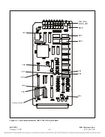
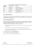
Figure 7-1. RFL 9785 Transmitter Module
7.1
DESCRIPTION
The RFL 9785 Transmitter Module (Figure 7-1) is a programmable powerline carrier transmitter,
utilizing Direct Digital Synthesis (DDS). The basic principle of DDS is to generate a stepped sine
wave from a high speed digital-to-analog (D/A) converter by reading a sine look-up table stored in
ROM. If the voice option is installed in the system, the output of the DDS is amplitude modulated to
the audio signal input. The output of the DDS is fed into an anti-aliasing filter and the signal level is
adjusted to achieve the desired overall transmission power (10W, 3W or 1W output of the power
amplifier).
The desired output frequency is selected by programming a set of direct reading rotary switches.
The module has presets for the center frequency, a shift up, and a shift down. The module can provide
amplitude modulation in systems equipped with the voice option, and an input signal can be used to
disable the voice signal when desired. External signals also select the output level of the module
corresponding to 10W, 3W or 1W. An additional “Reserve” input can be used to further reduce
transmit power by 10% to 35% of normal. The output of the module can be totally disabled via an
input signal.
Nine LEDs display the module status at all times. They indicate which of the three frequencies are
selected and which output power level is in use. LEDs also indicate if the transmitter carrier, voice or
reserve is enabled.
RFL 9785
RFL Electronics Inc.
For specific component information at the board level please contact the factory with the board
part number and revision level.
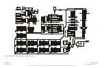
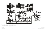
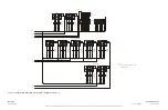
Transmitter Module Schematics are provided at the end of this
section.
April 25, 2005
7-1
(973) 334-3100