RFL 9785
RFL Electronics Inc.
July 26, 2007
16-4
(973) 334-3100
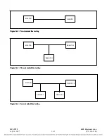
Figure 16-5b shows the checkback test routine used to test the two-terminal line shown in Figure 16-
5a. This routine has two basic steps:
1.
The Master sends Code 01 at full power (HIGH). The Remote receives Code 01, and sends
Code 01 back at full power (HIGH).
2.
The Master sends Code 02 at reduced power (LOW). The Remote receives Code 02, and sends
Code 02 back to the Master at reduced power (LOW).
Four different hard carrier requests can be initiated, as shown in Figure 16-5c:
1.
When the HC1 switch is pressed at the Master, Hard Carrier Request Code 03 is sent at full
power. The Remote receives this code, and sends a continuous hard carrier back at full power.
2.
When the HC1 switch is pressed at the Remote, Hard Carrier Request Code 04 is sent at full
power. The Master receives this code, and sends a continuous hard carrier back at full power.
3.
When the HC2 switch is pressed at the Master, Hard Carrier Request Code 05 is sent at full
power. The Remote receives this code, and sends a continuous hard carrier back at reduced
power.
4.
When the HC2 switch is pressed at the Remote, Hard Carrier Request Code 06 is sent at full
power. The Master receives this code, and sends a continuous hard carrier back at reduced
power.


