


19.4
ALARM RELAY I/O MODULE
ALARM RELAY
1 1
2 2
3 3
4 4
5 5
6 6
C
NO CHECKBACK TIP
NC
C
NO CHECKBACK FAIL
NC
C
POWER FAIL NO
NC
C
TX FAIL NO
NC
TB2
TB1
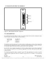
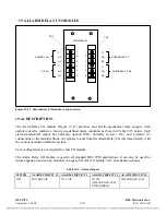
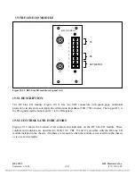
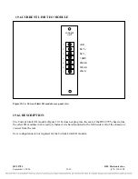
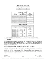
Figure 19-11. Alarm Relay I/O module, rear panel view
19.4.1
DESCRIPTION
The Alarm Relay I/O module (Figure 19-11) provides four electro-mechanical relay outputs. Each
output is used to indicate a factory pre-defined alarm condition as shown in Table 19-5 below. Each
electro-mechanical output has normally opened (NO), normally closed ( NC) and common (C)
connections at the terminal block. All signals to and from the Alarm Relay I/O interface directly with
the various modules within the system.
User configuration is not required for this I/O module.
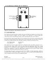
The Alarm Relay I/O module is used in all standard RFL 9785 applications. It can also be used for
future expansion and can be mounted in a spare I/O slot, if available, or in an expansion chassis.
Table 19-5. Alarm Outputs
SYSTEM
ALARM CIRCUIT #1 ALARM CIRCUIT #2
ALARM CIRCUIT #3 ALARM CIRCUIT #4
9785
POWER FAIL
TX FAIL
CB TIP
(CHECKBACK TEST
IN PROGRESS)
CHECKBACK FAIL
RFL 9785
RFL Electronics Inc.
September 1, 2006
19-23
(973) 334-3100