background image


https://www.hartmann-electronic.com/ 


Rev. 1.3 

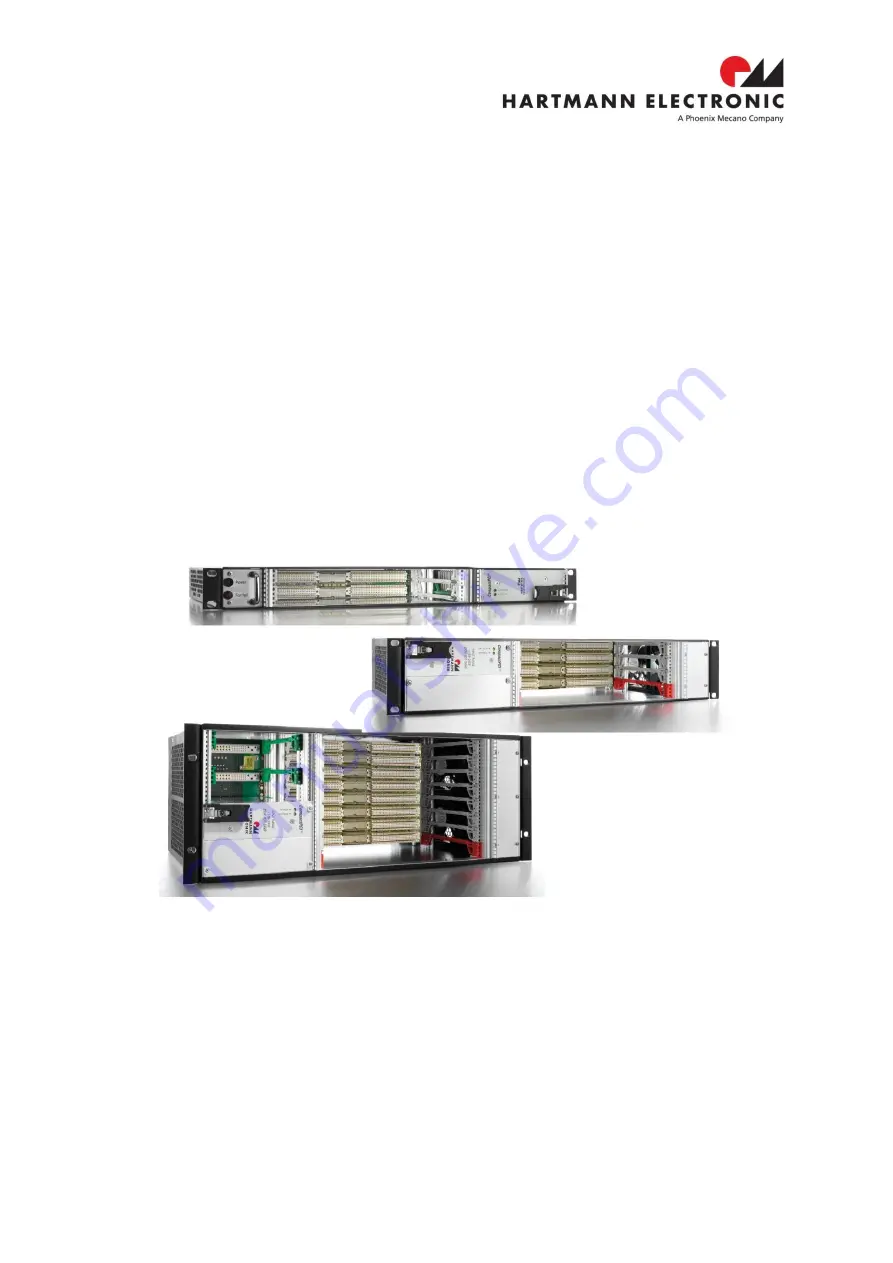
VME64x Basic 1U, 2U and 4U 

User's Manual


Содержание HARTMANN ELECTRONIC VME64x Basic 1U

Страница 1: ...https www hartmann electronic com Rev 1 3 VME64x Basic 1U 2U and 4U User s Manual...

Страница 2: ...Telefon 49 711 1 39 89 0 Telefax 49 711 8 66 11 91 E mail info hartmann electronic com Internet info hartmann electronic com Hartmann Electronic is a longstanding partner of the embedded industry and...

Страница 3: ...ith hot swap fan tray 6 3 1 5 VME64x Basic 4 U 84 HP 7 3 1 6 VME64x Basic 4 U 84 HP with hot swap fan tray 7 3 2 Subrack 8 3 3 Backplane 8 3 3 1 Description 8 3 3 2 Temperature sensors and fan control...

Страница 4: ...4 U 84 HP with hot swap fan try 7 Figure 3 7 Pin assignment fan signal connector 9 Figure 3 8 Dip Switch 9 Figure 3 9 Fan characteristic dip switch on off 10 Figure 3 10 Pin assignment fan signal conn...

Страница 5: ...Depth 283 mm with fan tray LMH0000260 1 1 Background Information User Manual Hartmann VME Backplanes Technical Data Hartmann VME Backplanes User Guide Hartmann VME Backplanes IEC 60297 3 101 ANSI VITA...

Страница 6: ...currently applicable in the country it is going to be used 2 2 Safety Symbols Hazardous voltage Familiarise yourself with the danger of electrical voltages and the safety precautions before starting...

Страница 7: ...subrack only with all free slots populated with filler panels Ensure that all EMI gaskets make correct contact 2 4 2 Electrostatic Discharge Precautions Electronic components can easily be destroyed b...

Страница 8: ...a high leakage current which is considered hazardous High leakage current can cause injuries Ensure that the system is properly grounded at all times the following conditions shall be met This equipme...

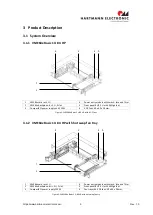
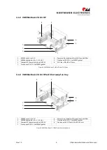
Страница 9: ...CompactPCI power supply unit 250 W 6 3 DC fans 40 x 40 x 28 mm Figure 3 1 VME64x Basic 1 U 84 HP with 4 DC fans 3 1 2 VME64x Basic 1 U 84 HP with hot swap fan tray 1 VME64x card rack 1U 4 Power entry...

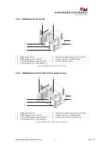
Страница 10: ...Front panel 8 HP 3 U with EMC gasket Figure 3 3 VME64x Basic 2 U 84 HP with 3 DC fans 3 1 4 VME64x Basic 2 U 84 HP with hot swap fan tray 1 VME64x card rack 2U 4 Power entry module with switch fuse an...

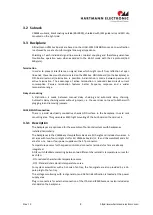
Страница 11: ...Front panel 8 HP 3 U with EMC gasket Figure 3 5 VME64x Basic 4 U 84 HP with 6 DC fans 3 1 6 VME64x Basic 4 U 84 HP with hot swap fan tray 1 VME64x card rack 4U 4 Power entry module with switch fuse an...

Страница 12: ...ining works without jumpers i e the user does not need to bother with plugging in and removing jumpers CHASSIS GND connection There is a solid electrically conductive chassis GND surface in the backpl...

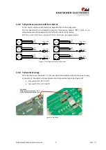
Страница 13: ...l GND NTC 1 Slot 1 Fan 2 12V GND Control GND NTC 2 Slot 2 Fan 3 12V GND Control GND NTC 3 Slot 3 Fan 4 12V GND Control GND NTC 4 Slot 4 Fan 5 12V GND Control GND NTC 5 Slot 5 Fan 6 12V GND Control GND...

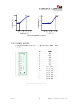
Страница 14: ...0 45 2900 min 1 1450 min 1 Figure 3 9 Fan characteristic dip switch on off 3 3 4 Fan signal connector For subracks assembled with a fan tray the fan signals are also provided by a 14 pole connector Fi...

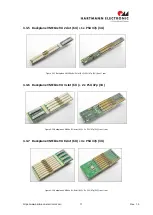
Страница 15: ...ure 3 11 Backplane VME64x 9U 2 slot 6U PSU 47p 3U front rear 3 3 6 Backplane VME64x 9U 4 slot 6U 2 x PSU 47p 3U Figure 3 12 Backplane VME64x 9U 4 slot 6U 2 x PSU 47p 3U front rear 3 3 7 Backplane VME6...

Страница 16: ...Class Suitable for appliances with protection class 1 acc to IEC 61140 Terminal Quick connect terminals 6 3 x 0 8 mm Panel Thickness s Screw on mounting max 8 mm Material Housing Thermoplastic black...

Страница 17: ...ividual components make contact with the gaskets and to the PE stud inside the rear panel The guide rails are also fitted with electrostatic discharge ESD contacts for each blade and RTM These ESD con...

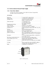
Страница 18: ...Available at FAL pin Status LED Green means valid input voltage Amber means a critical fault Thermal Protection OTP Installed NTC and thermostat for thermal sensor at DEG pin OUTPUT SPECIFICATION Out...

Страница 19: ...load with specified air flow Derates linearly to 50 at 70 C Storage Temperature 40 to 85 C Temperature Coefficient Typ 0 02 C Cooling At least 20 CFM 600 LFM moving air is required to achieve full ra...

Страница 20: ...ooled by forced air convection through up to six VDC axial fans The operating temperature is from 0 C to 40 C 3 5 1 Airflow Airflow from left to right Caution To ensure proper air flow within the syst...

Страница 21: ...HP Depth 283 mm with fan tray LMH0000260 40 x 40 x 28 mm fans are without speed control Different fans can be installed in the fan try Technical data DC fan 40 x 40 x 28 mm LMH0000200 Dimensions 40mm...

Страница 22: ...nchH2O Noise 46 6dB A Operating Temperature 10 C 60 C Non condensing Storage Temperature 30 C to 70 C Life Expectancy 40 000h Technical data DC fan 80 x 80 x 25 mm LMH0000170 LMH0000180 and LMH0000260...

Страница 23: ...ow 15 5 cfm 0 44 m min 51 5 cfm 1 46 m min Static Pressure 8 3 Pa 0 03 inchH2O 87 7 Pa 0 35 inchH2O Noise 17dB A 37dB A Operating Temperature 20 C 70 C Non condensing Storage Temperature 30 C to 70 C...

Страница 24: ...artmann electronic com 3 5 4 Fan Trays VME64x Basic 1 U Four DC fans 40 x 40 x 28 mm Figure 3 18 Fan Tray 1U VME64x Basic 2U Three DC fans 80 x 80 x 25 mm Figure 3 19 Fan Tray 2U VME64x Basic 4U Six D...

Страница 25: ...PCB s and connectors are used for electrical connection between the fan tray and the subrack In Subracks with build in fans the fans are connected to the 9U backplane 12V GND T Sense Fan Load 12V GND...

Страница 26: ...2 power supplies order no LMH0000260 a LMH0000180 One VME64x backplane compliant with ANSI VITA 1 1 1997specification 4 1 1 Controls and Indicators There are the following controls and indicators loca...

Страница 27: ...Ensure that the rack or cabinet is constructed to support the weight and dimensions of the system Incorrect system installation can cause the rack or cabinet to topple over additional stabilization m...

Страница 28: ...VITA 1 1994 specification WARNING Boards should slide easily when installing or removing them from the shelf Forcing the boards may cause damage to the interface connector pins 4 4 4 Installing Filler...

Страница 29: ...he front of the shelf until the interface connector disengages Wait until the fans have stopped and then remove the fan tray from the shelf Figure 5 1 Fan Tray Components sample 2U version WARNING Ext...

Страница 30: ...right hand side of the subrack Removing the Power Supply The steps required for removing the AC Power Supply as follows Loosen the two mounting screws left and right on the front of the AC Power Suppl...

Страница 31: ...https www hartmann electronic com 27 Rev 1 3...

Страница 32: ...tem platform Basic subracks are not end products with independent functionality according the EMC regulations therefore CE marking is not required Not before VME64x boards are plugged into the subrack...

Страница 33: ...connector switch fuse and filter 1 Partial front panel 8HP 16HP or 32HP 3U with EMC gasket with cutout for Power Entry module 1 Hot Swap Fan Tray for order numbers LMH0000310 LMH0000240 LMH0000260 3 D...

Страница 34: ...64x Basic 2U 3 x DC fans 80 x 80 x 25 mm 36 4 CFM 29 dB A VME64x Basic 4U 6 x DC fans 80 x 80 x 25 mm 36 4 CFM 29 dB A Temperature Operating 0 C to 40 C Storage 30 C to 70 C Transport 30 C to 70 C Hum...

Страница 35: ...https www hartmann electronic com 31 Rev 1 3 Regulatory Compliance EN60950 1...

Отзывы: