Intel iSBC 655, Hardware Reference Manual
The Intel iSBC 655 is a powerful single board computer with a range of features. For detailed information on how to utilize this product, users can download the Hardware Reference Manual for free from manualshive.com. This manual provides comprehensive instructions on operating and maximizing the potential of the iSBC 655.
Share
Download


Reviews:
No comments
Related manuals for iSBC 655

1404150
Brand: Global American Pages: 14

MYNX
Brand: Solid State Logic Pages: 52

IX2000
Brand: Viglen Pages: 58

FortiGate-7000F Series
Brand: Fortinet Pages: 63
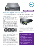
PowerEdge C5000
Brand: Dell Pages: 2

X-Sniper
Brand: Apevia Pages: 13

X-Jupiter
Brand: Apevia Pages: 12

SwitchBlade AT-SB4104-00
Brand: Allied Telesis Pages: 64

IES-5000 Series
Brand: ZyXEL Communications Pages: 72


