Global American 1404150, Quick Installation Manual
The Global American 1404150, a versatile and high-performance device, comes with a convenient Quick Installation Manual that guides users step-by-step through the setup process. This comprehensive manual is available for free download from our website, ensuring users have immediate access to hassle-free installation instructions.
Share
Download


Reviews:
No comments
Related manuals for 1404150

AISWITCH
Brand: Kentrox Pages: 306

Sun Storage J4200
Brand: Sun Microsystems Pages: 112
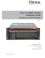
ValkyrieBay Val-C12-2400G
Brand: Xena Pages: 16

LC7.2E
Brand: Philips Pages: 111

LC4.41A AA
Brand: Philips Pages: 87

TE1.1E
Brand: Philips Pages: 46

TES1.0E LA
Brand: Philips Pages: 76

TPN15.2E LA
Brand: Philips Pages: 71

VES1.1E
Brand: Philips Pages: 79

LC8.1E
Brand: Philips Pages: 71

TPM16.1E LA
Brand: Philips Pages: 69

LC4.5E
Brand: Philips Pages: 80

Hummer Vault
Brand: nox Pages: 13

HUMMER NEXUS
Brand: nox Pages: 13

BANDIT II C2C
Brand: Encore Networks Pages: 8

IPC-622MS
Brand: Advantech Pages: 18

IPC-6806
Brand: Advantech Pages: 21

PCE-5B06-00A1E
Brand: Advantech Pages: 26


