23
0484-M002-0
6
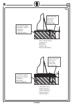
6. INSTRUCTIONS POUR LINSTALLATION
Le
pont
élévateur
doit
être
installé
sur
un
sol
plat
et
horizontal
à
m
ê
m
e
de
soutenir
les
CHARGES
TRANSMISES
AU
PLAN
DAPPUI
(voir
fi
g
ure
1
)
.
6.1 Conditions requises pour linstallation
A)
Béton
utilisé:
caté
g
orie
C
25
/
3
0
ou
supérieure
.
B)
Epaisseur
m
ini
m
u
m
du
sol
sans
considérer
tout
carrela
g
e
éventuel
avec
son
lit
de
po
se
(voir
fi
g
ure
1
a)
C)
Lar
m
ature
supérieure
et
inférieure
doivent
être
réalisées
au-
m
oins
avec
un
g
rilla
g
e
électrosoudé
Ø
4
x
1
5
0
mm
ou
équivalent,
dont
la
m
aille
ne
dépasse
pas
25
0
mm
.
La
couverture
en
béton
ne
doit
pas
excéder
les
25
mm
D)
Résistance
m
ini
m
ale
du
sol:
1
,
3
K
g
/c
m
2
Les
caractéristiques
que
nous
venons
dexposer
doivent
être
g
aranties
sur
une
surface
m
ini
m
ale
de
4,
00
x
1
,
5
0
m
(fi
g
.
1
)
qui
ne
doit
présenter
ni
joints
de
dilatations,
ni
coupures
pouvant
interro
m
pre
la
continuité
de
lar
m
ature
supérieure
.
6. INSTRUCCIONES PARA LA INSTALACIÓN
El
elevador
debe
instalarse
sobre
un
pavi
m
ento
plano
y
horizontal
capaz
de
soportar
las
CARGAS
TRANSMITIDAS
AL
PLANO
DE
APOYO
(ver
Fi
g
.
1
)
.
6.1 Requisitos para la instalación
A)
Hor
m
i
g
ón
e
m
pleado:
clase
C
25
/
3
0
o
superior
.
B)
Espesor
m
íni
m
o
del
piso
sin
considerar
los
posibles
revesti
m
ientos
de
baldosas
y
relativa
capa
de
asiento
(ver
Fi
g
.
1
a)
C)
Ar
m
adura
superior
e
inferior
realizada
con
red
electrosoldada
Ø
4x
1
5
0
mm
o
asi
m
ilable,
con
m
alla
no
superior
a
25
0
mm
.
Espesor
del
hor
m
i
g
ón
no
superior
de
25
mm
D)
Capacidad
de
car
g
a
m
íni
m
a
del
suelo:
no
inferior
a
1
,
3
K
g
/c
m
2
Las
características
arriba
m
encionadas
deben
estar
g
arantizadas
para
una
superfi
cie
m
íni
m
a
de
m
4,
00
x
1
,
5
0
(Fi
g
.
1
),
el
la
que
no
se
encuentren
juntas
de
dilatación
o
cortes
que
interru
m
pan
la
continuidad
de
la
ar
m
adura
superior
.
6. INSTALLATIONSANWEISUNGEN
Die
Hebebühne
m
uss
auf
eine
m
ebenen
und
waa
g
rechten
Boden
installiert
werden,
der
in
der
La
g
e
ist,
AUF
DIE
AUFLAGEFLÄCHE
ÜBERTRAGENE
BELASTUNGEN
(Siehe
Abb
.
1
)
.
6.1 Installationsanforderungen
A)
Beton:
Klasse
C
25
/
3
0
oder
h
ö
here
B)
Mindeststär
k
e
des
Bodenbela
g
s
ohne
Rüc
k
sicht
auf
eine
evtl
.
Fliesenver
k
leidun
g
und
entsprechenden
Unterbeton
(siehe
Abb
.
1
a)
C)
Obere
und
untere
Ar
m
ierun
g
m
indestens
m
it
ele
k
tro
g
eschweisste
m
Netz
Ø
4x
1
5
0
mm
oder
ähnliche
m
aus
g
eführt,
Raster
m
ax
.
25
0
mm
,
Betonstär
k
e
bis
zu
m
Eisen
g
erüst
m
ax
.
25
mm
D)
Mindestbelastbar
k
eit
des
Bodens
1
,
3
K
g
/c
m
2
Die
an
g
e
g
ebenen
Ei
g
enschaften
m
üssen
auf
einer
Mindestfläche
von
4,
00
x
1
,
5
0
m
(Abb
.
1
)
g
arantiert
werden,
auf
der
k
einerlei
Dehnun
g
sfu
g
en
oder
Risse
vorhanden
sein
dürfen,
die
die
Kontinuität
der
oberen
Ar
m
ierun
g
unterbrechen
würden
.
6. INSTALLATION INSTRUCTIONS
The
lift
should
be
installed
on
flat
level
floor
able
to
support
LOADS
TRANSMITTED
TO
SUPPORT
AREA
(See
fi
g
.
1
)
.
6.1 Installation requirements
Mini
m
u
m
features
foor
floor
should
be
the
followin
g
:
A)
Concrete
used:
class
C
25
/
3
0
or
hi
g
her
B)
Mini
m
u
m
thic
k
ness
of
the
floorin
g
net
of
any
tilin
g
and
layout
bloc
k
s
(See
fi
g
.
1
a)
C)
Upper
and
lower
reinforce
m
ent
done
at
least
with
electro-welded
wire
net
Ø
4x
1
5
0
mm
or
co
m
bined,
and
m
esh
not
exceedin
g
25
0
mm
.
Wire
cover
no
g
reater
than
25
c
m
D)
Bearin
g
capacity
of
area
no
less
than
1
,
3
K
g
/c
m
2
These
characteristics
m
ust
be
g
uaranteed
over
a
m
ini
m
u
m
area
of
m
4,
00
x
1
,
5
0
(fi
g
.
1
),
where
there
m
ust
be
no
expansion
joints
or
cuts
to
brea
k
the
continuity
of
the
upper
reinforce
m
ent
.
6. ISTRUZIONI PER LINSTALLAZIONE
Il
sollevatore
deve
essere
installato
su
pavi
m
ento
piano
e
orizzontale
in
g
rado
di
re
gg
ere
i
CARICHI
TRASMESSI
AL
PIANO
DAPPOGGIO
(vedi
fi
g
.
1
)
.
6.1 Requisiti per l'installazione
Le
caratteristiche
di
m
ini
m
a
della
pavi
m
entazione
debbono
essere:
A)
Calcestruzzo
utilizzato:
classe
C
25
/
3
0
o
superiore
B)
Spessore
m
ini
m
o
della
pavi
m
entazione
al
netto
di
eventuale
piastrellatura
e
relativo
m
assetto
di
posa
(vedi
fi
g
.
1
a)
C)
Ar
m
atura
superiore
ed
inferiore
realizzata
al
m
eno
con
rete
elettrosaldata
Ø
4
x
1
5
0
mm
o
assi
m
ilabile,
e
m
a
g
lia
non
superiore
a
25
0
mm
.
Copriferro
non
m
a
gg
iore
di
25
mm
D)
Portanza
del
terreno
non
m
inore
di
1
,
3
K
g
/c
m
2
Le
caratteristiche
esposte
debbono
essere
g
arantite
su
di
unarea
m
ini
m
a
di
m
4,
00
x
1
,
5
0
(fi
g
.
1
),
nella
quale
non
debbono
essere
presenti
g
iunti
di
dilatazione
o
ta
g
li
che
interro
m
pano
la
continuità
dellar
m
atura
superiore
.
Содержание VARKPH 370.32/T
Страница 7: ...7 0484 M002 0 0...
Страница 26: ...26 0484 M002 0 6 D C B A FUNI IDRAULICA B 1 2 600 kg 20 kg...
Страница 28: ...28 0484 M002 0 6 1 2 3 4 5 6 1 5...
Страница 34: ...34 0484 M002 0 H vedi see layout n 6 viti Screw Flex Hose Fune Rope 3b 3c 3d H vedi see layout 100 mm 6...
Страница 36: ...36 0484 M002 0 6 Fune Rope Fune Rope Flex Hose 5a 5b 5c Flex Hose...
Страница 40: ...40 0484 M002 0 6 F1 3 5 X 140 mm F1 F1 F1 F1 F1 8a F1 F1 8b...
Страница 41: ...41 0484 M002 0 6 10a 10b 9b V1 9 V V1 9a V...
Страница 44: ...44 0484 M002 0 6 ATTENZIONE WARNING ACHTUNG ATTENTION CUIDADO...
Страница 46: ...46 0484 M002 0 6 MIN MAX...
Страница 50: ...50 0484 M002 0 7 1 2 ATTENZIONE WARNING ACHTUNG ATTENTION CUIDADO 3 4...
Страница 54: ...54 0484 M002 0 9...


