Measurements and Results
R&S
®
FSVA3000/ R&S
®
FSV3000
144
User Manual 1178.8520.02 ─ 01
The R&S
FSV/A software allows you to perform ACLR measurements on input con-
taining multiple signals for different communication standards. A measurement stan-
dard is provided that allows you to define multiple discontiguous transmit channels at
specified frequencies, independent from the selected center frequency. The ACLR
measurement determines the power levels of the individual transmit, adjacent, and gap
channels, as well as the total power for each sub block of transmit channels.
A detailed measurement example is provided in
Chapter 7.3.7, "Measurement Exam-
7.3.2
Channel Power Results
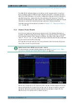
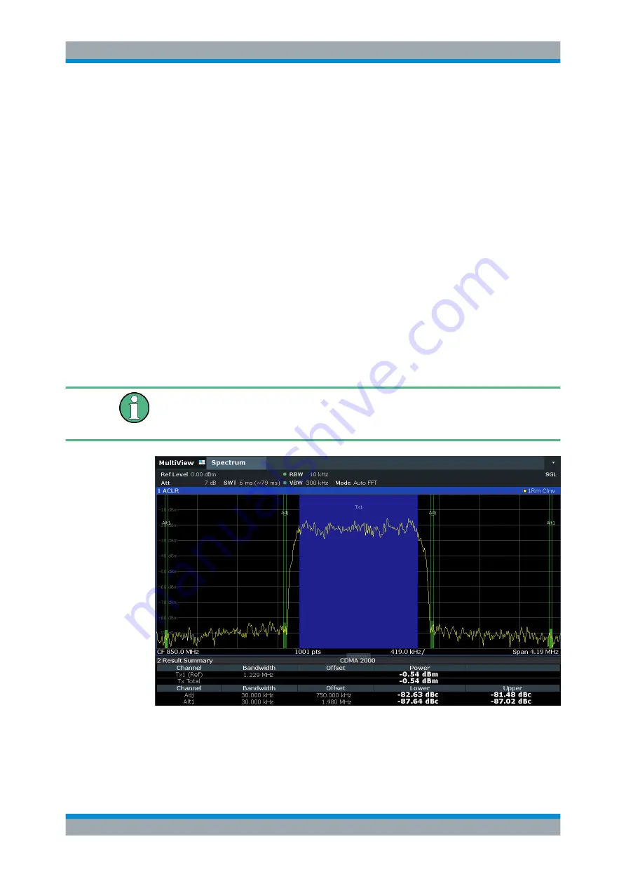
For channel or adjacent-channel power measurements, the individual channels are
indicated by different colored bars in the diagram. The height of each bar corresponds
to the measured power of that channel. In addition, the name of the channel ( "Adj" ,
"Alt %1" , "Tx %1" , etc., or a user-defined name) is indicated above the bar (separated
by a line which has no further meaning).
For "Fast ACLR" measurements, which are performed in the time domain, the power
versus time is shown for each channel.
Multi-standard radio (MSR) channel power results
The channel power results for MSR signals are described in
surement on Multi-Standard Radio (MSR) Signals"
Results are provided for the TX channel and the number of defined adjacent channels
above and below
the TX channel. If more than one TX channel is defined, you must
specify the channel to which the relative adjacent-channel power values refer. By
default, it is the TX channel with the maximum power.
Channel Power and Adjacent-Channel Power (ACLR) Measurement


