
2
About the XLS
XLS Library Technical Service Manual
2-
17
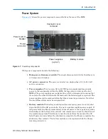
Power System
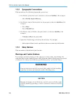
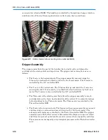
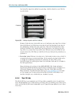
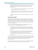
Figure 2-7
shows the power components accessible from the rear of the LRM.
Cosmetic cover
removed
Power switch/
breaker
Power
connector
Power supplies
(up to 7)
Battery module
Figure 2-7
Power bay components
XLS power components include the following:
•
Main power disconnect switch.
The single disconnect switch for the library is
a 20-amp circuit breaker.
•
AC power connector.
The power connector is a single-phase, 100 to 240 volt
service connection.
•
Power supplies.
Two to seven AC-to-24VDC power supply modules provide
power to the components within the LRM, the tape drives, and any attached
MEMs. The power supplies are configured in an N+1 arrangement, meaning that
if one fails, the others will handle the load until the failed supply is replaced. The
power supplies can be replaced while the library remains powered on. Note that
the two leftmost slots must be occupied first.
•
Battery module.
The battery module provides emergency power to safely shut
down the XLS if the AC power fails. It is not an uninterruptible power supply. If
AC power fails, the library immediately shuts off power to the tape drives, parks
the handler at the bottom of the cabinet, and commences an orderly shut down of
the remaining systems. The library is non-functional from the moment the AC
fails. If power returns before the shutdown is complete, the library completes the
shutdown, then restarts. The battery module can be replaced while the library
remains powered on.
Содержание XLS Series
Страница 1: ...Technical Service Manual Document No 501610 Rev 07 01 19 XLS Series of Tape Libraries...
Страница 14: ...501610 Rev 07 01 19 Part I Before You Begin Notes...
Страница 58: ...3 7 Cabling for the Carousel Controller 3 12 501610 Rev 07 01 19 Notes...
Страница 70: ...4 5 Inspecting and Cleaning the Gripper and Barcode Reader 4 12 501610 Rev 07 01 19 Notes...
Страница 72: ...Part II Using X Link 501610 Rev 07 01 19 Notes...
Страница 96: ...Part III Replacing FRUs 501610 Rev 07 01 19 Notes...
Страница 136: ...8 8 Bringing a Tape Drive Online 8 14 501610 Rev 07 01 19 Notes...
Страница 158: ...9 5 Replacing a Drive Bay with a Cartridge Bay 9 22 501610 Rev 07 01 19 Notes...
Страница 172: ...10 3 Replacing a Side Panel 10 14 501610 Rev 07 01 19 Notes...
Страница 186: ...11 3 Upgrading a Fixed Port Assembly to an I O Port 11 14 501610 Rev 07 01 19 Notes...
Страница 226: ...12 6 Replacing the Y Motor Assembly 12 40 501610 Rev 07 01 19 Notes...
Страница 324: ...Part IV Reference 501610 Rev 07 01 19 Notes...
Страница 352: ...B 2 Packing the XLS B 14 501610 Rev 07 01 19 Notes...
Страница 354: ...C 2 501610 Rev 07 01 19 Notes...
Страница 360: ...Glossary GL 6 501610 Rev 07 01 19 Notes...
Страница 366: ...Index IN 6 501610 Rev 07 01 19 Notes...


