A–15
Power Paper Stacker Maintenance
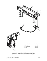
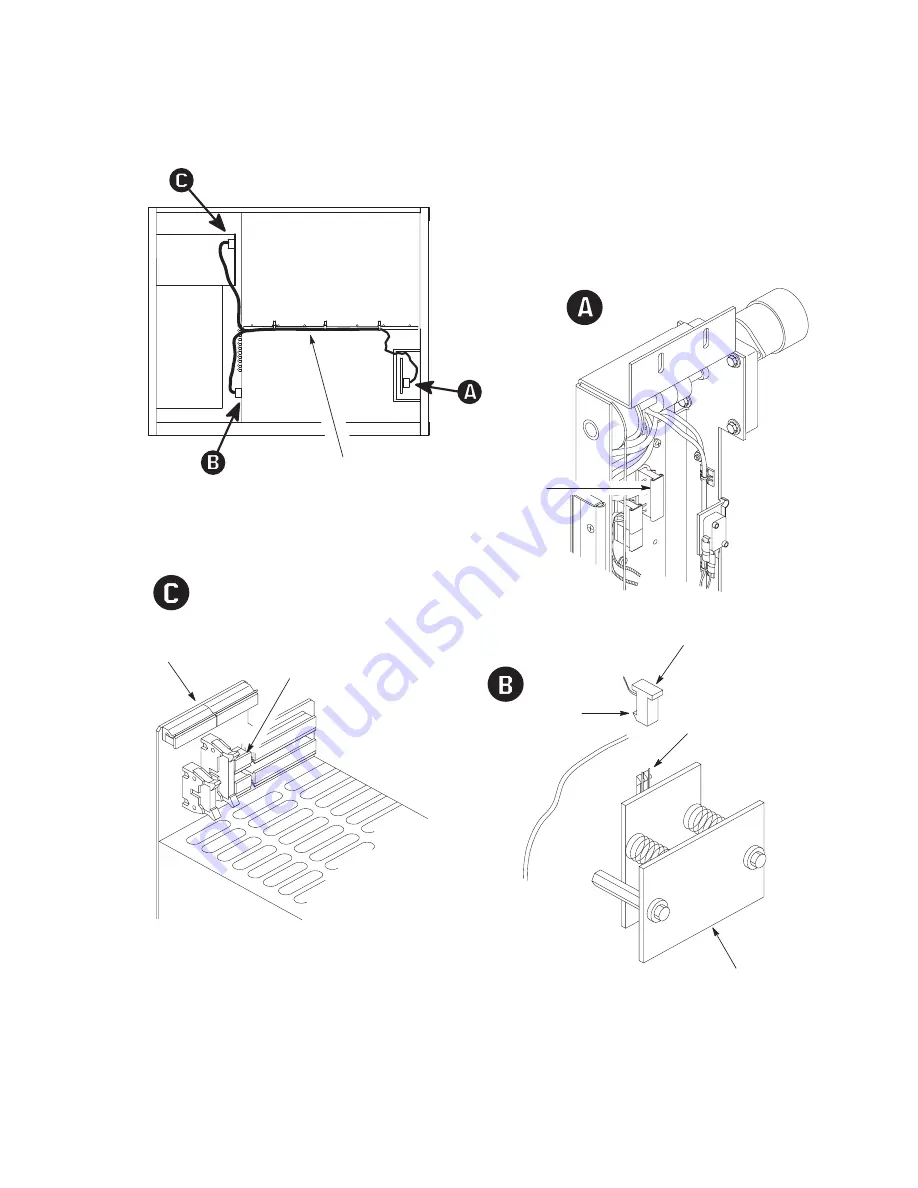
PRINTER TOP VIEW
(Cutaway)
6
7
1
(REAR)
1. Logic Cable Assembly
133783–001
2. Connector P3
Part of item 1
3. Connector P1
Part of item 1
4. Connector J1
Part of item 5
5. Emitter
133669–901
6. Connector P19
Part of item 1
7. Logic Backplane
133885–001
8. Locking Tab
Part of item 3
3
8
4
5
2
Figure A–7. Logic Cable Removal/Installation
Содержание P9012
Страница 1: ...P N 132305 001 Rev E P9012 Multifunction Line Printer...
Страница 49: ...2 31 Principles of Operation Power Supply PCBAs 1 3 SHORT OPEN Figure 2 21 Power Supply PCBA...
Страница 53: ...2 35 Principles of Operation PAPER FEED MOTOR TRACTORS PAPER TRANSPORT Figure 2 26 Paper Feed Components...
Страница 58: ...2 40 Principles of Operation...
Страница 84: ...4 18 Troubleshooting...
Страница 107: ...5 23 Alignments and Adjustments 1 Screw 2 MPU Arm 1 2 Figure 5 9 Magnetic Pickup Phasing Adjustment...
Страница 118: ...5 34 Alignments and Adjustments...
Страница 203: ...6 85 Replacement Procedures This page intentionally left blank...
Страница 214: ...6 96 Replacement Procedures...
Страница 217: ...A 3 Power Paper Stacker Maintenance Printer Rear Power Paper Stacker Figure A 1 Power Paper Stacker...
Страница 236: ...A 22 Power Paper Stacker Maintenance...
Страница 246: ...D 2 Torque Table...
Страница 254: ...Index 6...
Страница 255: ......
Страница 256: ...132305 001 Rev E...


