6–88
Replacement Procedures
AC Power Bus Assembly
(Figure 6–28)
Removal
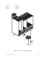
1. Remove the card cage as described on page 6–76.
2. Remove two screws (1) and the insulator (2) in three places.
3. Remove the AC power bus assembly (3) from the card cage (4).
Installation
1. Place the AC power bus assembly on the card cage.
2. Install two screws and the insulator in three places.
3. Install the card cage as described on page 6–84.
Содержание P9012
Страница 1: ...P N 132305 001 Rev E P9012 Multifunction Line Printer...
Страница 49: ...2 31 Principles of Operation Power Supply PCBAs 1 3 SHORT OPEN Figure 2 21 Power Supply PCBA...
Страница 53: ...2 35 Principles of Operation PAPER FEED MOTOR TRACTORS PAPER TRANSPORT Figure 2 26 Paper Feed Components...
Страница 58: ...2 40 Principles of Operation...
Страница 84: ...4 18 Troubleshooting...
Страница 107: ...5 23 Alignments and Adjustments 1 Screw 2 MPU Arm 1 2 Figure 5 9 Magnetic Pickup Phasing Adjustment...
Страница 118: ...5 34 Alignments and Adjustments...
Страница 203: ...6 85 Replacement Procedures This page intentionally left blank...
Страница 214: ...6 96 Replacement Procedures...
Страница 217: ...A 3 Power Paper Stacker Maintenance Printer Rear Power Paper Stacker Figure A 1 Power Paper Stacker...
Страница 236: ...A 22 Power Paper Stacker Maintenance...
Страница 246: ...D 2 Torque Table...
Страница 254: ...Index 6...
Страница 255: ......
Страница 256: ...132305 001 Rev E...

