background image

5–2

Alignments and Adjustments

Alignments and Adjustments

This chapter contains the alignment and adjustment procedures done at

the field service maintenance level.

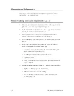
Ribbon Tracking Check and Adjustment 

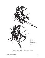
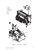
(Figure 5–1)

1. Make sure paper is loaded in the printer and a full ribbon spool is on the

right. Turn power on and open the printer top cover.

2. Set the forms thickness adjustment lever (1) to any position between “A”

and “B.” Make sure no error indications appear.

3. Refer to the P9012 User’s Manual and command a shuttle/ribbon

self–test. Shuttle action and ribbon motion should begin.

4. On either the left or right ribbon guide (2), momentarily short across the

skids (3).

5. Let the ribbon run completely out of the spool. Verify the ribbon is

centered in the guide. If not, follow these steps:

a.

Loosen two screws (4) with washers (5) until the left ribbon guide

can be rotated about the guide post (6).

b. Pivot the guide until the ribbon tracks in the center.

c.

Tighten two screws.

d. Verify that the ribbon is centered and winds up without interference

on the left spool.

6. The spool should automatically reverse. If it does not, follow these steps:

a.

Replace the ribbon (page 6–8). Rerun the test.

b. If there is still an error, check the cabling.

c.

If ribbon tracking is still unsuccessful, replace the ribbon deck

assembly (page 6–8).

Содержание P9012

Страница 1: ...P N 132305 001 Rev E P9012 Multifunction Line Printer...

Страница 2: ...s digital apparatus does not exceed the Class A limits for radio noise emissions from digital apparatus set out in the radio interference regulations of the Canadian Department of Communications Ce ma...

Страница 3: ...ptional Features 1 6 Control Panel Switches and Indicators 1 7 Mechanical Controls 1 10 I O Panel 1 12 Tools Test Equipment and Supplies 1 13 2 Principles of Operation Chapter Contents 2 1 Scope 2 2 P...

Страница 4: ...Printing 2 38 Self Test 2 38 3 Scheduled Maintenance Chapter Contents 3 1 Preventive Maintenance Checks and Services PMCS 3 2 Inspecting the Printer 3 3 Cleaning the Printer 3 4 Exterior of Cabinet 3...

Страница 5: ...ten Gap 5 18 Magnetic Pickup Gap 5 20 Magnetic Pickup Phasing Adjustment 5 22 Shuttle Belt Tension 5 24 Paper Feed Belt Tension 5 26 Paper Motion Sensor 5 28 Paper Out Detector 5 32 6 Replacement Proc...

Страница 6: ...r Out Switch 6 66 Platen Open Switch 6 68 Exhaust Fan 6 70 DCU MCU Mechanism Driver PCBAs 6 72 Hammer Driver and Power Supply PCBAs 6 74 Card Cage 6 76 Card Cage Fan 6 86 AC Power Bus Assembly 6 88 DC...

Страница 7: ...1 1 Overview 1 Overview Chapter Contents About This Manual 1 2 Description 1 4 Control Panel Switches and Indicators 1 6 Mechanical Controls 1 8 I O Panel 1 10 Tools Test Equipment and Supplies 1 11...

Страница 8: ...air the P9012 printer You can locate maintenance information three ways Use the Table of Contents at the front of the manual Use the Chapter Contents list on the first page of each chapter Use the Ind...

Страница 9: ...uppercase letters Example Press the CLEAR switch to take the printer to the OFFLINE READY state Related Documents For additional information about printer configuration and operation and optional inte...

Страница 10: ...trix line printer In addition to basic functions the printer can produce correspondence quality print for near letter quality NLQ printing requirements draft print for higher speed and character attri...

Страница 11: ...nt International Character Sets Resident OCR A and OCR B Character Sets Downloadable Character Sets Built in Self Tests and Diagnostics Configuration Printout Datastream Hex Code Printout Ribbon Fault...

Страница 12: ...control panel operation ON LINE ON LINE CLEAR 6 8 LPI PAPER ADV CHECK 8 LPI VFU LOADED MENU UP MENU DOWN NEXT PREV RUN STOP ENTER F L PRINT MODE HOLD ENABLE REPRINT PA1 CANCEL PA2 ALT MODE These switc...

Страница 13: ...other than 6 lpi PAPER ADV switch Press momentarily to advance the paper one line Press and hold to advance the paper to the next top of form VFU LOADED indicator Illuminates when the format is being...

Страница 14: ...Figure 1 3 Control or Indicator Function 1 Forms Thickness Adjustment Lever Sets the platen for different thickness forms or paper Open raise fully for loading paper 2 Forms Thickness Scale and Point...

Страница 15: ...Overview 3 2 1 4 5 6 1 Forms Thickness Adjustment Lever 2 Forms Thickness Scale Pointer 3 Horizontal Adjustment Knob 4 Tractor Lock 2 5 Vertical Adjustment Knob 6 Tractor 2 Figure 1 3 Mechanical Contr...

Страница 16: ...serial and parallel interfaces Figure 1 4 shows the I O panel on the rear of the printer 1 RS 232 Serial Connector 2 AC On Off Switch 3 AC Power Connector 4 Dataproducts Parallel Connector 5 Centronic...

Страница 17: ...1805 001 Nut Driver Set Xcelite P2120 Oscilloscope and Probes 35 MHz Pliers Grip Ring Truarc 1120 Pliers Chain Nose Erem 11DH Ratchet 3 8 in Drive Rule Steel 6 in General 616 Scale Spring 0 to 40 lbs...

Страница 18: ...1 12 Overview Item Recommended Item Part Number Shims Counterweight 101564 001 Shims Shuttle Assembly 103422 001 Socket 7 16 in 3 8 in Drive Soldering Iron and Tips X acto Knife and Blades...

Страница 19: ...nts 2 9 Control Panel 2 12 Data Control Unit DCU PCBA 2 14 Mechanism Control Unit MCU PCBA 2 18 Mechanism Driver PCBA 2 22 Hammer Driver PCBA 2 25 Hammer Bank and Shuttle Mechanics MPU 2 28 Power Supp...

Страница 20: ...er also provides illustrations which show the location of test points on the P9012 PCBAs For a complete list of signal mnemonics mentioned in this chapter refer to Appendix C Purpose The P9012 printer...

Страница 21: ...e next Figure 2 1 and Figure 2 2 With spacing of eight lines per inch there are nine dot rows per character line for nine lines per inch there are eight dot rows per character line and for spacing of...

Страница 22: ...CASE WITH DESCENDER Figure 2 2 Typical Characters DOT COLUMN DOT ROW WITH UNDERLINE 1 3 5 7 9 1 2 2 3 3 4 4 5 5 6 6 7 7 8 8 9 PRINTED UNDERLINE WITH UNDERLINES WITHOUT UNDERLINES DOT COLUMN DOT ROW 1...

Страница 23: ...ached at one end to the hammer bank with a screw Figure 2 4 The end opposite the screw has a pointed tip attached A permanent magnet keeps all the hammers retracted and under tension Each hammer has a...

Страница 24: ...2 6 Principles of Operation PERMANENT MAGNET HAMMER HAMMER SPRING COIL COIL COIL COIL DE ENERGIZED ENERGIZED NORMAL RETRACTED STATE ACTIVATED RELEASE STATE TIP Figure 2 5 Print Hammer Action...

Страница 25: ...6 and Figure 2 7 DOT ROW START PAPER ADVANCES PAPER FEED PAPER ADVANCES SPACE 1 2 3 4 5 6 7 8 9 10 11 12 1 2 USED FOR LOWERCASE DESCENDER ONLY USED FOR UNDERLINE AND LOWERCASE DESCENDER ONE CHARACTER...

Страница 26: ...TER AREA AND CHARACTER SPACE HAMMER POSITIONS ARE NOT ILLUSTRATED IN THIS DIAGRAM NOTE DOT NO DOT WHERE HAMMER HAS BEEN HAMMER POSITION 1 1 1 3 1 3 5 3 5 7 1 3 5 7 9 DOT COLUMN 1 1 2 1 2 3 1 2 3 4 1 2...

Страница 27: ...Data Control Unit DCU PCBA Mechanism Control Unit MCU PCBA Mechanism Driver PCBA Hammer Driver PCBA s Hammer Bank and Shuttle Mechanics Magnetic Pickup MPU Power Supply PCBA s Ribbon Deck Paper Trans...

Страница 28: ...nciples of Operation PCBAs RIBBON DECK TRACTOR Paper Transport PAPER OUT SWITCH PLATEN OPEN SWITCH SHUTTLE MOTOR MPU Shuttle Mechanics CONTROL PANEL HAMMER BANK SHUTTLE Figure 2 8 Printer Functional E...

Страница 29: ...ANK TO DCU AND MCU HSC FAULT STATUS DCU MESSAGE READY READ MESSAGE DO D7 MOTOR CONTROL FAULTS SENSE PAPER DRIVE SHUTTLE DRIVE RIBBON DRIVE PLATEN OPEN PAPER OUT PAPER MOTION FAULT IL AIR POWER SUPPLY...

Страница 30: ...alphanumeric display as well as status information For a detailed discussion of panel operation refer to the P9012 User s Manual ON LINE ON LINE CLEAR 6 8 LPI PAPER ADV CHECK 8 LPI VFU LOADED MENU UP...

Страница 31: ...2 13 Principles of Operation CONTROL PANEL PCBA PANEL DCU SWITCH CLOSURES SW CLOSURES STATUS CONTROL PANEL ASSEMBLY DATA CONTROL Figure 2 11 Control Panel Block Diagram...

Страница 32: ...s then taken from the ASCII format to the format used in the dot image buffer DIB Software determines the special character attributes and any special handling of the data in the DIB due to the contro...

Страница 33: ...2 15 Principles of Operation DCU PCBA Slot 3 TP4 12VDC TP3 12VDC TP2 VCCP5 TP1 GND J5 J6 J1 Serial I O J2 Parallel I O Figure 2 12 Data Control Unit DCU PCBA...

Страница 34: ...U DATA CNTL DTACK H O S T D M A A D D R E S S 18 16 ADDRESS DECODE BUS ARBITRATION CONTROL CNTLS DECODE AND BUFFER DTACK GENERATOR DATA BUS PARALLEL I F DMA CONTROLLER 68B44 PARITY CHECK CONTROL CODE...

Страница 35: ...OE DATA BUS STATUS REGISTER P R I N T H N O H NSWITCH 5V GND ADDRESS BUS 23 16 PDATA NPFAULT REGSEL NENABLE NSWITCH NPCLK NPLOAD COM HSCK 5VDC 12VDC 12VDC GND E A D S E L E C T A0 A1 8 PARALLEL AND SE...

Страница 36: ...h signals sent to the hammer driver and mechanism driver PCBAs The board is controlled by a microprocessor It contains three sections of memory timers and control ports in order to control hammer firi...

Страница 37: ...2 19 Principles of Operation MCU PCBA Slot 4 TP1 5VDC TP2 GND TP3 PPR BUSY TP4 SDIR P7 P8 Figure 2 14 Mechanism Control Unit MCU PCBA...

Страница 38: ...AND MCU DCU COMMAND PORT 4 X 8 MCU R DCU W DIP SWITCH HAMMER DRIVER TEST PORT HAMMER DRIVER STATUS PORT COLOR CONTROL PORT 4 4 H A M M E R D R I V E R I O 4 4 4 X 8 DCU R MCU W BD0 7 BD0 7 D4 7 BD0 3...

Страница 39: ...BD0 3 FIRE 0 1 2 D0 3 D4 7 PAPER FEED FIRE CONTROL LOGIC I F I F DCU I F DRIVER I F RIBBON CONTROL 3 PF1 2 4 PF3 4 NHCK NUD HRS DCMOD MECH DRIVER I F NFLT NPLAO NPADO NRIBFLT PMD FAULT I F AIRFLT IL B...

Страница 40: ...are under control of the MCU The mechanism driver PCBA also produces by use of switching regulators the 12 V and 5 VDC required by the MCU and DCU These voltages are generated from the 36 V output of...

Страница 41: ...P25 58V TP5 12V TP4 63V TP3 36V TP2 MPU TP1 PMD TP11 PF1 CHOP TP10 VREF TP9 PF2 CHOP TP23 SHT PROP TP22 HES A TP24 SHT INTEG TP21 HES RET 12V TP13 12V TP15 12V J9 J10 Note All voltages shown are in VD...

Страница 42: ...OTOR MECHANISM DRIVER PCBA GND 36 12 MCU PCBA MPU _ _ 12VDC IN 5V IN MASTER CLEAR MPU MPU 36VDC 36V RTN 5VDC GUIDES SWR SWL PAPER TRANSPORT RIBBON DRIVE SHUTTLE MECHANICS FILE FAULT DETECT RIB MOV RIB...

Страница 43: ...egister by the rising edge of NHSC containing dot information for the characters to be printed by each hammer After the last bit is clocked into the shift register the next SYNC pulse causes hammer cl...

Страница 44: ...26 Principles of Operation Hammer Driver PCBAs 1 3 TP10 8V TP1 5V TP7 12V TP8 OD TP2 COM1 TP3 HCK TP6 36V TP4 NHSCB TP5 HRS TP9 COMOUT Note All voltages shown are in VDC Figure 2 18 Hammer Driver PCB...

Страница 45: ...RLINGTON DRIVERS 33 DATA LATCHES 33 SHIFT REGISTER 33 CK 12V t t t t Q Q ISOLATORS OPTO 12V RTN 36V HMC NHCK HRS COM IN NHSC HRS COM IN NHSC OE HCK 5HL SD 12V NUD t t 36V OD D Q CK ISOLATOR OPTO COM O...

Страница 46: ...with the shuttle starting to move from left to right Full rotation of the disk provides eight printing periods and four back and forth shuttle cycles Each printing period is followed by a turnaround p...

Страница 47: ...timers CLK and applied to print synchronizing logic on the MCU PCBA Typical signal levels received from the magnetic pickup are SYNC 2 5 to 5 5 Vpp RESYNC 4 Vpp minimum SHUTTLE MOTOR Shuttle Mechanic...

Страница 48: ...operation or an overload condition the power supply will recover so that power may be reapplied in less than 2 5 seconds If an overload occurs the power supply will return to the normal operation les...

Страница 49: ...2 31 Principles of Operation Power Supply PCBAs 1 3 SHORT OPEN Figure 2 21 Power Supply PCBA...

Страница 50: ...nsioned by the application of NRIBEN from the MCU PCBA When NRIBMOV is applied the ribbon will move NRIBMOV is applied when DCMOD comes on starting the shuttle The NRIBMOV and NRIBEN signals enable ga...

Страница 51: ...CH 5V 27V 36V NSD RH LH LOW HIGH 5V K1 M1 K2 M2 5V Q1 Q2 3 7V 5V END OF RIBBON DETECTORS RC RS1 RIN1 R F1 RIN2 R F2 R S2 1V TO 5V VOLTAGES ARE AS INDICATED WHEN RIBBON IS RUNNING FROM RIGHT TO LEFT 17...

Страница 52: ...e to the top of form to a selected vertical tab or by being put under EVFU control the corresponding profile of paper movement velocity is selected by the MCU to obtain precise paper control Paper is...

Страница 53: ...2 35 Principles of Operation PAPER FEED MOTOR TRACTORS PAPER TRANSPORT Figure 2 26 Paper Feed Components...

Страница 54: ...er that the printer is out of paper or the platen has been left open When either signal is detected paper transport is disabled and the ribbon loses tension The signal faults are reported to the contr...

Страница 55: ...ed to the hammer driver board the OE line is held low 5V 12V voltages levels are out of tolerance Two other circuits monitor the leakage currents of both the overdrive transistor and the lower hammer...

Страница 56: ...dot image buffer Information from the dot image buffer is synchronized with printer requirements using the magnetic pickup signal then shifted out to hammer drivers The selected hammers are fired When...

Страница 57: ...SELECT FROM FRONT PANEL SYNCHRONIZE THE TIMING TO THE CODE WHEEL MPU SOFTWARE MCU DEMAND HAMMER LOAD MCU DATA SHIFTED OUT TO HAMMER DRIVER DCU FIRE HAMMERS ON NEXT MPU ALL DOTS IN ROW PRINTED N Y MOV...

Страница 58: ...2 40 Principles of Operation...

Страница 59: ...3 1 Scheduled Maintenance 3 Scheduled Maintenance Chapter Contents Preventive Maintenance Checks and Services PMCS 3 2 Inspecting the Printer 3 3 Cleaning the Printer 3 4...

Страница 60: ...rinting or if it is located in a dusty area PMCS are listed in Table 3 1 WARNING Disconnect the AC power cord before performing PMCS Failure to do so could result in injury to you or damage to the equ...

Страница 61: ...ens closes smoothly and damper struts hold cover open Hinges Inspect for damage and loose or missing hardware Electrical connectors Inspect for damage and bent or broken pins Controls and indicators I...

Страница 62: ...at the sides of the cabinet Interior of Cabinet Figure 3 1 1 Set the AC power switch on the rear of the printer to the O OFF position 2 Disconnect the the AC power cord from the rear of the printer a...

Страница 63: ...t Lever 2 Lock Tab 2 3 Ribbon Spool 2 4 Ribbon Hub 2 5 Tractor 2 6 Hammer Bank 7 Base Casting 8 Splined Shaft 9 Ribbon Guide 10 Paper Motion Detector 11 Ribbon Path 12 Platen 5 7 10 4 3 2 1 11 12 6 un...

Страница 64: ...pen Remove any paper present 3 Squeeze the lock tabs 2 and remove the ribbon spools 3 from the ribbon hubs 4 Slide the right tractor 5 fully to the right 4 Remove the ribbon deck 6 as described on pag...

Страница 65: ...stment Lever 2 Lock Tab 2 3 Ribbon Spool 2 4 Ribbon Hub 2 5 Right Tractor 6 6 Ribbon Deck 7 Hammer Bank 8 Ribbon Mask 9 Hammer Bank Cover 10 Platen 11 Hammer Springs 12 Hammer Tips 4 3 1 5 6 8 11 2 10...

Страница 66: ...tenance 8 Install the ribbon deck as described on page 6 8 of Chapter 6 Replacement Procedures 9 Install the ribbon spools on the ribbon hubs Replace paper 10 Close the cover and return the printer to...

Страница 67: ...ubleshooting 4 Troubleshooting Chapter Contents Introduction 4 2 Fault Messages 4 2 Symptoms Not Indicated by Fault Messages 4 11 Diagnostic Self Tests 4 14 Running the Self Tests 4 16 Hex Code Printo...

Страница 68: ...ition occurs The second line of the display indicates the specific fault NOTE The alarm can be turned off before the fault is cleared by pressing the CLEAR switch There are two types of displayed faul...

Страница 69: ...g an operator correctable fault press the CLEAR switch before placing the printer on line If any other fault messages appear without an asterisk press the CLEAR switch to continue However if this prob...

Страница 70: ...d by an asterisk next to the message FONT PROM HAMMER DR PCB X X 1 2 or 3 NOVRAM PROGRAM PROM If HAMMER DR PCB X appears on the display printer power will automatically shut off 10 seconds after the f...

Страница 71: ...one at a time in the following order until the message disappears mechanism driver MCU PCBA sensor blower FONT PROM Instruction Indication Yes No 1 Set power switch to O OFF Wait 5 seconds Set power...

Страница 72: ...hammers 60 88 2 controls 30 60 3 controls 1 30 Return printer to normal operation 4 Run a diagnostic self test page 4 14 HAMMER DR PCB X message Replace one at time until the message disappears power...

Страница 73: ...with cotton swab Go to step 7 Return printer to normal operation 5 Set the paper motion sensor fault setting to DISABLE See the P9012 User s Manual PAPER JAM message Return printer to normal operation...

Страница 74: ...age Replace paper out switch assembly page 6 66 Return printer to normal operation PLATEN OPEN Instruction Indication Yes No 1 Load paper Step 2 2 Close forms thickness adjustment lever Step 3 3 Run a...

Страница 75: ...GRAM PROM message Replace the program PROM chips on the DCU PCBA Return printer to normal operation RIBBON Instruction Indication Yes No 1 Wind the ribbon by hand and check for folds tears holes frayi...

Страница 76: ...mal operation 4 Run a shuttle ribbon test SHUTTLE STALL message Step 5 Return printer to normal operation 5 Check for a broken or damaged shuttle belt Belt is damaged Replace the shuttle belt page 6 4...

Страница 77: ...ield replaceable assemblies b Start at a general level and work down to details 4 Replace the defective part or assembly IMPORTANT Do not attempt field repairs on electronic components or assemblies r...

Страница 78: ...pins on card cage logic backplane PCBA If broken replace card cage logic backplane PCBA page 6 94 Step 3 3 Power up printer and check display and card cage fan operation Display comes on Resume printi...

Страница 79: ...on is correct for the user s application b Host computer and printer use the same protocol emulation c Configuration has not been inadvertently changed by the user Step 6 Reconfigure the printer See U...

Страница 80: ...ertical compression Shuttle assembly Hammer bank cover Hammer spring All E s A pattern of all uppercase letter E s useful for identifying missing characters misplaced dots smeared characters improper...

Страница 81: ...Underlines An underline pattern useful for identifying hammer bank misalignment Mechanism driver or MCU PCBA Hammer back cover Hammer tips Paper feed motor or belt Splined shaft bearings Tractor bear...

Страница 82: ...select one of the 8 INCH WIDTH or FULL WIDTH paper tests press MENU DOWN then repeatedly press NEXT or PREV until the appropriate test is displayed Tests include shift recycle all E s and others 5 Pre...

Страница 83: ...ASCII character equivalents perform the following steps 1 Place the printer off line and raise the printer cover 2 Press MENU DOWN repeatedly press NEXT or PREV until DIAGNOSTICS is displayed 3 Press...

Страница 84: ...4 18 Troubleshooting...

Страница 85: ...Height Adjustment 5 4 Setting Shuttle and Counterweight Preload 5 6 Shuttle and Counterweight Spring Adjustment 5 10 Hammer Spring Retensioning 5 14 Hammer Tip Alignment 5 16 Platen Gap 5 18 Magnetic...

Страница 86: ...ribbon motion should begin 4 On either the left or right ribbon guide 2 momentarily short across the skids 3 5 Let the ribbon run completely out of the spool Verify the ribbon is centered in the guide...

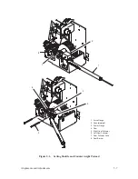
Страница 87: ...3 Alignments and Adjustments 1 Forms Thickness Adjustment Lever 2 Right Ribbon Guide 3 Right Guide Skid 2 4 Screw 2 5 Washer 2 6 Guide Post 1 4 6 3 2 5 Figure 5 1 Ribbon Tracking Check and Adjustment...

Страница 88: ...queeze the lock tabs 1 and remove the ribbon spools 2 from the hubs 3 3 Check the distance between the bottom of the hub and the gearbox 4 The hub should just clear the gearbox 4 If the clearance is i...

Страница 89: ...5 5 Alignments and Adjustments 1 Lock Tab 2 2 Ribbon Spool 2 3 Hub 2 4 Gearbox 5 Setscrew 5 4 1 3 2 Figure 5 2 Ribbon Hub Height Adjustment...

Страница 90: ...Remove the dust barrier 8 5 Insert the force gauge 1 in the hole in the counterweight 2 6 Insert a 0 003 inch flat feeler gauge 3 between the cam 4 and the right cam follower 5 7 Pull the force gauge...

Страница 91: ...s and Adjustments 1 Force Gauge 2 Counterweight 3 Feeler Gauge 4 Cam 5 Right Cam Follower 6 Left Cam Follower 7 Cam Follower Yoke 8 Dust Barrier 1 2 3 4 6 7 8 5 Figure 5 3 Setting Shuttle and Counterw...

Страница 92: ...pring shim and repeat steps 8 through 10 11 Operate the printer a Run the printer for 10 minutes using a shuttle ribbon fast test Check for rattle and increase the preload if necessary b Run the print...

Страница 93: ...s and Adjustments 1 Force Gauge 2 Counterweight 3 Feeler Gauge 4 Cam 5 Right Cam Follower 6 Left Cam Follower 7 Cam Follower Yoke 8 Dust Barrier 1 2 3 4 6 7 8 5 Figure 5 3 Setting Shuttle and Counterw...

Страница 94: ...spect the area around the shuttle spring 4 and the counterweight spring 5 for shims that may have broken or come loose Replace any loose shims per steps 6 and 7 below 4 Set the AC power switch to the...

Страница 95: ...nd Adjustments 1 Screw 2 2 Cam Cover 3 Gasket 4 Shuttle Spring 5 Counterweight Spring 6 Counterweight 7 Yoke 8 Shim 9 Screw 10 Shim 11 Casting 4 6 7 9 8 11 2 1 3 10 hidden 5 Figure 5 4 Shuttle Spring...

Страница 96: ...shim 10 c Install a shim between the spring spacer and the casting 11 d Tighten the screw 8 Operate the printer a Run the printer for 10 minutes using a shuttle ribbon fast test Check for rattle and...

Страница 97: ...nd Adjustments 1 Screw 2 2 Cam Cover 3 Gasket 4 Shuttle Spring 5 Counterweight Spring 6 Counterweight 7 Yoke 8 Shim 9 Screw 10 Shim 11 Casting 4 6 7 9 8 11 2 1 3 10 hidden 5 Figure 5 4 Shuttle Spring...

Страница 98: ...n flexing the spring 3 Restore the printer to the normal operating configuration by performing the hammer spring installation procedure as described on page 6 24 of Chapter 6 Replacement Procedures Pr...

Страница 99: ...5 15 Alignments and Adjustments 1 Hammer Spring 2 Pole Pin 3 Hammer Tip PRINT TOO LIGHT PRINT TOO DARK 1 1 2 3 Figure 5 5 Hammer Spring Retensioning...

Страница 100: ...mmer bank in the service position 3 Loosen the screw 1 of the hammer spring 2 to be aligned 4 Place the alignment tool 3 P N 132266 001 over the hammer tips Move the hammer spring until the tip is in...

Страница 101: ...5 17 Alignments and Adjustments 1 Screw 2 Hammer Spring 3 Alignment Tool P N 132266 001 3 2 1 Figure 5 6 Hammer Tip Alignment...

Страница 102: ...ithin six hammer positions of the left end of the hammer bank If the forms thickness adjustment lever is in the A position use a 0 009 inch feeler gauge When the lever is fully closed use a 0 007 inch...

Страница 103: ...5 19 Alignments and Adjustments 1 Forms Thickness Lever 2 Feeler Gauge 3 Platen 4 Hammer Tip 5 Hammer Bank Cover 6 Set Screw 2 3 6 1 6 2 5 4 hidden Figure 5 7 Platen Gap Adjustment...

Страница 104: ...ck to see that the flywheel axle is against the rear roll pin 3 Loosen the two captive screws and remove the cam cover 1 4 Loosen the clamping screw 2 to allow the MPU 3 to be rotated 5 Set the gap be...

Страница 105: ...5 21 Alignments and Adjustments 1 Cam Cover 2 Screw 3 MPU 4 Flywheel Sync Windows 5 Flat Feeler Gauge 4 5 3 2 1 Figure 5 8 Magnetic Pickup Gap Adjustment...

Страница 106: ...e P9012 User s Manual and command a 132 column self test printing all H s Observe the printout The relative horizontal position of dots in alternate rows should be as shown below If either incorrect c...

Страница 107: ...5 23 Alignments and Adjustments 1 Screw 2 MPU Arm 1 2 Figure 5 9 Magnetic Pickup Phasing Adjustment...

Страница 108: ...am cover 1 3 Observe the shuttle belt 2 and press down with your finger in the middle using about 2 oz of force 4 If the belt deflection is significantly more or less than 0 21 inches 5 3 mm perform t...

Страница 109: ...5 25 Alignments and Adjustments 1 Cam Cover 2 Shuttle Belt 3 Nut 4 4 Motor 0 21 in DEFLECTION 3 4 2 1 Figure 5 10 Shuttle Belt Tension Check and Adjustment...

Страница 110: ...tension as described below 5 Install the belt guard and two screws 6 Close the printer cover Adjustment 1 Remove the lower paper guide as described on page 6 56 of Chapter 6 Replacement Procedures CAU...

Страница 111: ...5 27 Alignments and Adjustments 1 Screw 2 2 Belt Guard 3 Paper Feed Belt 4 Screw 4 5 Motor 0 0625 in DEFLECTION 3 4 5 1 2 Figure 5 11 Paper Feed Belt Tension Check and Adjustment...

Страница 112: ...a 2 inch section of paper including the holes from the edge of the paper below the left tractor Advance the torn section of the paper through the tractor An error message should appear This indicates...

Страница 113: ...nts and Adjustments 8 1 Left Tractor 2 Nut 3 Washer 4 Clamp 5 Paper Motion Sensor 6 Cable 7 Capacitor C19 8 Mechanism Driver PCBA 1 2 3 4 6 5 6 5 TP6 7 C19 Figure 5 12 Paper Motion Sensor Test and Pos...

Страница 114: ...peak to peak If the amplitude is less than 150 mV loosen the mounting nut 2 and move the sensor toward or away from the paper until a maximum signal level is obtained Some high gain sensors will provi...

Страница 115: ...nts and Adjustments 8 1 Left Tractor 2 Nut 3 Washer 4 Clamp 5 Paper Motion Sensor 6 Cable 7 Capacitor C19 8 Mechanism Driver PCBA 1 2 3 4 6 5 6 5 TP6 7 C19 Figure 5 12 Paper Motion Sensor Test and Pos...

Страница 116: ...ickness settings anywhere between A and C Adjustment 1 Load paper and apply power 2 Set the forms thickness adjustment lever 1 to the fully closed position 3 Rotate the shaft 2 until the space between...

Страница 117: ...5 33 Alignments and Adjustments 1 Forms Thickness Lever 2 Shaft 3 Nylon Button 4 Platen 1 4 hidden 3 2 Figure 5 13 Paper Out Detector Check and Adjustment...

Страница 118: ...5 34 Alignments and Adjustments...

Страница 119: ...6 6 Ribbon Deck 6 8 Ribbon Control PCBA 6 10 Ribbon Drive Motor 6 14 Blower and Airflow Assembly 6 16 Shuttle Assembly 6 18 Hammer Spring 6 22 Hammer Coil 6 28 Counterweight Assembly 6 32 Flywheel As...

Страница 120: ...66 Platen Open Switch 6 68 Exhaust Fan 6 70 DCU MCU and Mechanism Driver PCBAs 6 72 Hammer Driver and Power Supply PCBAs 6 74 Card Cage 6 76 Card Cage Fan 6 86 AC Power Bus Assembly 6 88 DC Power Bus...

Страница 121: ...or the shuttle assembly Some part numbers listed in this chapter contain a 901 extension This extension designates a field replaceable item The part number for the actual production part contains a 00...

Страница 122: ...l 1 Raise the top cover 2 Loosen two captive screws 1 3 Lift the right side panel 2 off of the support pins 3 and remove the panel from the printer Installation CAUTION When installing the right side...

Страница 123: ...6 5 Replacement Procedures 1 2 3 1 Screw Captive 2 140593 001 2 Right Side Panel 140477 003 3 Support Pin 2 N A Figure 6 1 Side Panel Removal Installation...

Страница 124: ...o free the cable 3 5 Remove four screws 4 6 Remove the control panel assembly 5 from the bracket 6 Installation 1 Feed the cable through the hole in the bracket and place the control panel assembly on...

Страница 125: ...rocedures 1 2 3 4 5 6 1 Connector N A 2 Card Cage Logic Backplane 133885 901 3 Cable Part of item 5 4 Screw 4 N A 5 Control Panel Assembly 131434 901 6 Bracket 131592 001 Figure 6 2 Control Panel Remo...

Страница 126: ...d remove the ribbon spools 4 from the ribbon hubs 5 3 Remove two hex head screws 6 4 Raise the ribbon deck assembly slightly and lift it off the retaining clips 7 5 Remove the ribbon deck assembly fro...

Страница 127: ...2 7 3 4 1 1 Connector 2 N A 2 Ribbon Deck Assembly 131883 903 3 Lock Tab 2 Part of item 3 4 Ribbon Spool 2 N A 5 Ribbon Hub 2 102526 001 6 Screw 2 140113 001 7 Retaining Clip 2 101302 001 Figure 6 3 R...

Страница 128: ...ers from the ribbon deck housing 4 4 Disconnect connector J45 5 from shunt plug P45 6 5 Disconnect connectors 7 and 8 from PCBA connectors RMJ1 9 and RGJ1 10 6 Disconnect connectors 11 and 12 from PCB...

Страница 129: ...ctor Part of item 19 8 Connector Part of item 19 9 Connector RMJ1 Part of item 19 10 Connector RGJ1 Part of item 19 11 Connector Part of item 19 12 Connector Part of item 19 13 Connector RMJ2 Part of...

Страница 130: ...tion the ribbon control PCBA in the ribbon deck housing 2 Mount the PCBA to the ribbon deck housing with the four hex screws 17 and flat washers 18 3 Attach connectors J30 and J33 to the ribbon deck h...

Страница 131: ...ctor Part of item 19 8 Connector Part of item 19 9 Connector RMJ1 Part of item 19 10 Connector RGJ1 Part of item 19 11 Connector Part of item 19 12 Connector Part of item 19 13 Connector RMJ2 Part of...

Страница 132: ...sembly 7 4 Disconnect the motor cable connector 8 from the ribbon control PCBA 9 5 Remove two screws 10 and washers 11 6 Separate the motor from the ribbon deck assembly Installation 1 Place the motor...

Страница 133: ...e 131306 001 4 Screw 102786 605 5 Washer 101526 002 6 Cover 131694 001 7 Ribbon Deck Assembly 131883 903 8 Motor Cable Connector Part of item 3 9 Ribbon Control PCBA 132335 901 10 Screw 2 101513 016 1...

Страница 134: ...ower Installation 1 Position the blower in the printer cabinet 2 Install three screws lockwashers and washers 3 Attach the airflow hose assembly to the blower outlet boot and secure with the hose clam...

Страница 135: ...3 Screw 3 102998 001 4 Lockwasher 3 102158 002 5 Washer 3 101526 003 6 Hose Clamp 141532 001 7 Airflow Hose Assembly 133445 902 8 Outlet Boot Part of item 9 9 Blower 131907 901 10 Hose Clamp 141532 00...

Страница 136: ...two captive screws 2 and remove the cam cover 3 5 Remove six screws 4 the cam front cover plate 5 and the gasket 6 6 Remove two screws 7 lockwashers 8 and the dust barrier block 9 7 Disconnect the coi...

Страница 137: ...5 Front Cover Plate 131580 001 6 Gasket 131492 001 7 Screw 2 101541 057 8 Lockwasher 2 102158 001 9 Dust Barrier Block 133442 001 10 Coil Connector Part of item 15 11 Screw 2 101514 009 12 Lockwasher...

Страница 138: ...ews Over tightening will strip the threads in the casting and the casting will require replacement 4 Working from left to right connect the coil connectors 5 Install the dust barrier block two screws...

Страница 139: ...5 Front Cover Plate 131580 001 6 Gasket 131492 001 7 Screw 2 101541 057 8 Lockwasher 2 102158 001 9 Dust Barrier Block 133442 001 10 Coil Connector Part of item 15 11 Screw 2 101514 009 12 Lockwasher...

Страница 140: ...emove two screws 9 and washers 10 from the shroud 11 g Separate the shroud from the shuttle assembly 12 CAUTION Be careful to prevent shims and the antirotation block from falling into the printer h R...

Страница 141: ...r 2 101526 003 9 Screw 2 101524 025 10 Washer 2 102158 005 11 Shroud 131998 001 12 Shuttle Assembly 131419 904 13 Screw 2 101514 054 14 Antirotation Block 131494 001 15 Shim 131493 001 16 Hammer Bank...

Страница 142: ...e clean and free of burrs 2 Install screw 19 finger tight Align the hammer tips as described on page 5 16 of Chapter 5 Alignments and Adjustments 3 Return the hammer bank to the operating position by...

Страница 143: ...r 2 101526 003 9 Screw 2 101524 025 10 Washer 2 102158 005 11 Shroud 131998 001 12 Shuttle Assembly 131419 904 13 Screw 2 101514 054 14 Antirotation Block 131494 001 15 Shim 131493 001 16 Hammer Bank...

Страница 144: ...d f are followed to prevent wear on the front of the shroud Incorrect placement can also cause poor print quality Inspect the front area of the shroud to ensure that there is adequate clearance betwee...

Страница 145: ...r 2 101526 003 9 Screw 2 101524 025 10 Washer 2 102158 005 11 Shroud 131998 001 12 Shuttle Assembly 131419 904 13 Screw 2 101514 054 14 Antirotation Block 131494 001 15 Shim 131493 001 16 Hammer Bank...

Страница 146: ...s any more than necessary to remove the leads Damage to the connector will result a Using an X acto knife or other small tool push down the releasing tab 3 b Withdraw the coil lead and its terminal 4...

Страница 147: ...rt of item 4 4 Terminal Part of item 11 5 Screw 2 105947 001 6 coil Lead Clamp 131937 001 7 Coil Lead Bracket 131934 001 8 Screw 101514 056 9 Washer 101526 039 10 Coil Clamp Plate 132001 001 11 Coil 1...

Страница 148: ...e coil leads under the coil lead clamp Install the two clamp screws 5 but do not tighten 4 Install the leads into the coil connector Make sure the sense of color coding is identical with other coils a...

Страница 149: ...rt of item 4 4 Terminal Part of item 11 5 Screw 2 105947 001 6 Coil Lead Clamp 131937 001 7 Coil Lead Bracket 131934 001 8 Screw 101514 056 9 Washer 101526 039 10 Coil Clamp Plate 132001 001 11 Coil 1...

Страница 150: ...front cover plate 4 and the gasket 5 5 Loosen one screw 11 about three turns but DO NOT remove it at this time 6 Using a hex tipped screwdriver push on screw 11 to relieve the spring force on the shim...

Страница 151: ...Cam Cover Plate 131580 001 5 Gasket 131492 001 6 Screw 3 101514 041 7 Lockwasher 3 102158 002 8 Washer 3 101526 003 9 Lockwasher 102158 002 10 Shim 101564 001 11 Screw 101514 041 12 Washer 101526 003...

Страница 152: ...loose about three turns 4 Using a hex tipped screwdriver push on screw 11 and install the shim s 5 Tighten screw 11 6 Install the cam front cover plate gasket and six screws 3 7 Set the counterweight...

Страница 153: ...Cam Cover Plate 131580 001 5 Gasket 131492 001 6 Screw 3 101514 041 7 Lockwasher 3 102158 002 8 Washer 3 101526 003 9 Lockwasher 102158 002 10 Shim 101564 001 11 Screw 101514 041 12 Washer 101526 003...

Страница 154: ...Do not adjust the MPU clamp screw as it affects the MPU gap 2 Back out the screw 1 about 25 inch 3 Move the MPU arm 2 away from the flywheel 3 as far as the support plate 4 allows 4 Remove two screws...

Страница 155: ...1240 001 3 Flywheel Assembly 131865 903 4 Support Plate 101132 001 5 Screw 2 101514 042 6 Lockwasher 2 102158 002 7 Shuttle Belt 101768 003 8 Base Support 132288 001 9 Roll Pin 101556 005 10 Cam Part...

Страница 156: ...el a few times to align the belt to to the grooves in the flywheel 6 Partially install the counterweight assembly as described on page 6 34 steps 1 through 5 7 Move the MPU arm toward the flywheel unt...

Страница 157: ...1240 001 3 Flywheel Assembly 131865 903 4 Support Plate 101132 001 5 Screw 2 101514 042 6 Lockwasher 2 102158 002 7 Shuttle Belt 101768 003 8 Base Support 132288 001 9 Roll Pin 101556 005 10 Cam Part...

Страница 158: ...one screw 1 and bracket 2 3 Remove the cam wick 3 and discard Installation 1 Using a heavy cloth moistened with isopropyl alcohol remove all metal shavings from the flywheel assembly 4 and base suppor...

Страница 159: ...6 41 Replacement Procedures 1 2 3 4 5 1 Screw 140113 001 2 Bracket 132070 001 3 Cam Wick 132072 001 4 Flywheel Assembly 131865 903 5 Base Support 132288 001 Figure 6 12 Cam Wick Removal Installation...

Страница 160: ...nector P35 1 5 Loosen the MPU clamping screw 2 Unscrew the MPU 3 from the MPU arm 4 and remove it from the printer Installation 1 Screw the MPU into the MPU arm until it is about half a turn from the...

Страница 161: ...3 Replacement Procedures 1 3 4 5 2 1 Connector P35 Part of item 2 2 Screw 101514 037 3 MPU 131301 001 4 MPU Arm 101240 001 5 Flywheel Assembly 131865 903 Figure 6 13 Magnetic Pickup Removal Installati...

Страница 162: ...uide 4 3 Loosen two screws 5 4 Separate the cam cover 6 and the attached gasket 7 from the base support 8 5 Loosen four nuts 9 Allow the motor 10 to slip down 6 Slip the belt 11 off the motor pulley 1...

Страница 163: ...8 001 6 Cam Cover 140269 001 7 Gasket 106963 001 8 Base Support 132288 001 9 Nut 4 101525 010 10 Shuttle Motor 131168 901 11 Shuttle Belt 101768 003 12 Motor Pulley Part of item 10 13 Connector P34 Pa...

Страница 164: ...P34 and P40 4 Slip the belt over the motor pulley 5 Check and adjust the shuttle belt tension as described on page 5 24 of Chapter 5 Alignments and Adjustments 6 Position the cam cover with attached...

Страница 165: ...8 001 6 Cam Cover 140269 001 7 Gasket 106963 001 8 Base Support 132288 001 9 Nut 4 101525 010 10 Shuttle Motor 131168 901 11 Shuttle Belt 101768 003 12 Motor Pulley Part of item 10 13 Connector P34 Pa...

Страница 166: ...ve the flywheel assembly as described on page 6 36 2 Remove the belt 1 from the shuttle motor pulley 2 Make sure the pulley is not loose on the shaft Installation 1 Place the belt over the shuttle mot...

Страница 167: ...6 49 Replacement Procedures 1 2 1 Shuttle Belt 101768 003 2 Shuttle Motor Pulley N A Figure 6 15 Shuttle Belt Removal Installation...

Страница 168: ...ed on page 6 18 3 Loosen the four paper ironer mounting screws 1 4 Slip the paper ironer 2 up and out from under the plate 3 and remove 5 Remove any paper chaff from the paper ironer mounting area Ins...

Страница 169: ...6 51 Replacement Procedures 2 Platen 1 Screw 2 101514 061 2 Paper Ironer 102677 002 3 Plate 131413 001 Figure 6 16 Paper Ironer Removal Installation...

Страница 170: ...rd 2 4 Loosen the setscrew 3 in the bushing 4 5 Slide the bushing off the splined shaft 5 6 Shift the splined shaft to the right until the bearing 6 is free of the right side plate 7 NOTE If the belt...

Страница 171: ...101143 002 5 Splined Shaft 108653 001 6 Bearing Part of item 5 7 Right Side Plate 131147 002 8 Screw 4 101514 063 9 Paper Feed Motor 131302 901 10 Paper Feed Belt 108664 001 11 Motor Pulley Part of i...

Страница 172: ...nstall the bushing on the shaft 6 Set the bushing 0 001 to 0 005 inches from the left side plate 13 7 Align the pulley on the splined shaft with the motor pulley Center the belt on the motor pulley 8...

Страница 173: ...101143 002 5 Splined Shaft 108653 001 6 Bearing Part of item 5 7 Right Side Plate 131147 002 8 Screw 4 101514 063 9 Paper Feed Motor 131302 901 10 Paper Feed Belt 108664 001 11 Motor Pulley Part of i...

Страница 174: ...nuts 11 6 Slip the belt 12 off the motor pulley 13 7 Separate the motor 14 from the right side plate 15 Installation 1 Place the motor against the right side plate 2 Slip the belt over the motor pull...

Страница 175: ...001 5 Connector J32 Part of item 14 6 Screw 2 102786 610 7 Belt Guard 132312 001 8 Screw 4 101514 063 9 Washer 4 102158 005 10 Washer 4 101526 002 11 Nut 4 102788 600 12 Paper Feed Belt 108664 001 13...

Страница 176: ...the tractor support shaft plate 15 7 Unscrew the support shaft 8 until it clears the knob 9 8 To remove the right tractor a Slide the splined shaft to the right and slip the belt 10 off the motor feed...

Страница 177: ...aft 108653 001 6 Screw 102786 605 7 Washer 101526 002 8 Support Shaft 102095 002 9 Knob 102100 001 10 Paper Feed Belt 108664 001 11 Motor Pulley N A 12 Screw 106708 001 13 Cable Clamp 102049 006 14 Sc...

Страница 178: ...ations 18 on the upper inside shaft mount of each tractor Make sure that the marks on one tractor line up with the marks on the other otherwise the paper will feed incorrectly d Slide the splined shaf...

Страница 179: ...aft 108653 001 6 Screw 102786 605 7 Washer 101526 002 8 Support Shaft 102095 002 9 Knob 102100 001 10 Paper Feed Belt 108664 001 11 Motor Pulley N A 12 Screw 106708 001 13 Cable Clamp 102049 006 14 Sc...

Страница 180: ...page 6 4 3 Unlock the right tractor 1 and the left tractor 2 4 Remove one screw 3 and washer 4 5 Unscrew the support shaft 5 from the knob 6 6 Move the support shaft to the right until it clears the l...

Страница 181: ...8616 902 2 Left Tractor 108616 904 3 Screw 102786 605 4 Washer 101526 002 5 Support Shaft 102095 002 6 Knob 102100 001 7 Nut 102788 400 8 Washer 101526 005 9 Retainer 106565 001 10 Sensor 102057 001 1...

Страница 182: ...are visible If not loosen the screws and reposition as necessary 5 Move the support shaft to the left and into the left tractor 6 Screw the support shaft into the knob 7 Install one screw and washer...

Страница 183: ...8616 902 2 Left Tractor 108616 904 3 Screw 102786 605 4 Washer 101526 002 5 Support Shaft 102095 002 6 Knob 102100 001 7 Nut 102788 400 8 Washer 101526 005 9 Retainer 106565 001 10 Sensor 102057 001 1...

Страница 184: ...r end of the switch assembly 4 and remove it from the front of the belt cover 5 Installation 1 Slip the switch assembly into position through the front of the belt cover 2 Install two screws 3 Connect...

Страница 185: ...ment Procedures 1 Connector P41 Part of item 4 2 Cable Assembly Part of item 4 3 Screw 2 102786 406 4 Switch Assembly 131281 001 5 Belt Cover 131555 001 5 3 4 2 1 Figure 6 21 Paper Out Switch Removal...

Страница 186: ...itch 3 4 Remove two screws 4 washers 5 spacers 6 and nut plate 7 Installation 1 Connect the white lead and the red lead to the switch 2 Position the switch two spacers and the nut plate 3 Install two...

Страница 187: ...Procedures 1 2 4 5 3 6 7 1 White Lead N A 2 Red Lead N A 3 Switch 101867 007 4 Screw 2 102559 420 5 Washer 2 101526 009 6 Spacer 102132 010 7 Nut Plate 104960 001 Figure 6 22 Platen Open Switch Remov...

Страница 188: ...n page 6 4 3 Remove four screws 1 and the fan muffler 2 4 Disconnect the fan connector 3 5 Remove four screws 4 washers 5 and the fan 6 Installation 1 Install the exhaust fan four washers 5 and screws...

Страница 189: ...ent Procedures AIRFLOW 1 2 3 4 5 6 1 Screw 4 140113 003 2 Fan Muffler 131818 001 3 Connector Part of item 6 4 Screw 4 102786 628 5 Washer 4 101526 002 6 Fan 131913 001 Figure 6 23 Exhaust Fan Removal...

Страница 190: ...l PCBA with the replacement If the new board is a different firmware version refer to the P9012 User s Manual for configuration details b If the new board is the same firmware version remove any PROMs...

Страница 191: ...10W 002 Program PROMs 8P 001 and 10P 002 MCU Location Program PROM 6F 001 1 2 3 4 5 6 1 Screw 2 102786 608 2 Cover 133860 001 3 Connector N A 4 Ejection Lever 2 131268 001 5 PCBA as required DCU Slot...

Страница 192: ...locations are labelled at the top of the card cage Removal installation is the same for all cards The Power Supply 3 PCBA is illustrated 1 Remove the right side panel as described on page 6 4 2 Loose...

Страница 193: ...5 3 4 1 Screw 2 102786 608 2 Cover 131388 002 3 Ejection Lever 2 131268 001 4 PCBA as required Hammer Driver 131666 901 Power Supply 133546 902 5 Card Cage 133610 001 Figure 6 25 Hammer Driver Power S...

Страница 194: ...el as described on page 6 4 3 Loosen the four screws 1 which secure the two card cage covers 2 3 Do not remove the screws Remove the card cage covers by sliding them up and out 4 Disconnect the cables...

Страница 195: ...cement Procedures 2 3 5 4 ref 6 1 4 1 Screw 4 102786 608 2 Cover 133860 001 3 Cover 131388 002 4 Cables as required N A 5 Card Cage 133983 001 6 Clip 109822 002 Figure 6 26 Card Cage Removal Installat...

Страница 196: ...the printer cabinet b On the opposite side of the panel disconnect the seven terminal wires 9 from the circuit breaker 10 c Disconnect transformer connector P2 11 from J2 12 d Remove the nut I O pane...

Страница 197: ...Blue Brown Black Brown Black Blue Black 7 9 10 13 7 Rear I O Panel 131912 005 8 Screw 5 140113 003 9 Terminal 7 Part of item 10 10 Circuit Breaker 109520 001 11 Connector P2 N A 12 Connector J2 N A 13...

Страница 198: ...ted on the rear of the card cage To access these two screws open the rear door of the printer and look to the lower left side of the printer frame 7 Slide the card cage out of the printer cabinet as f...

Страница 199: ...placement Procedures 14 18 15 16 17 14 Screw 6 140113 003 15 Connector A R N A 16 Logic Backplane PCBA 133453 001 17 Connector P18 N A 18 Connector P17A N A Figure 6 26 Card Cage Removal Installation...

Страница 200: ...ire 19 from inside the printer cabinet This ground wire is attached to the same post as the I O panel ground wire Disengage the wire from the clips 12 Remove twelve screws 20 and the six hammer driver...

Страница 201: ...6 83 Replacement Procedures 19 20 21 19 Ground Wire N A 20 Screw 12 101513 001 21 Hammer Driver Connector 6 N A Figure 6 26 Card Cage Removal Installation 4 of 4...

Страница 202: ...he printer cabinet with a starwasher and nut Engage the wire in the clips 8 Secure the card cage with six screws 14 four in the front and two in the back 9 Install the I O panel as follows a Attach th...

Страница 203: ...6 85 Replacement Procedures This page intentionally left blank...

Страница 204: ...emoval 1 Remove the card cage as described on page 6 76 2 Remove four screws 1 and washers 2 3 Disconnect the connector 3 4 Separate the fan 4 from the card cage 5 Installation 1 Place the fan in the...

Страница 205: ...87 Replacement Procedures 1 2 5 3 4 AIRFLOW 1 Screw 4 102786 628 2 Washer 4 101526 002 3 Connector Part of item 4 4 Fan 131913 001 5 Card Cage 133610 001 Figure 6 27 Card Cage Fan Removal Installatio...

Страница 206: ...bed on page 6 76 2 Remove two screws 1 and the insulator 2 in three places 3 Remove the AC power bus assembly 3 from the card cage 4 Installation 1 Place the AC power bus assembly on the card cage 2 I...

Страница 207: ...6 89 Replacement Procedures 1 2 3 4 1 Screw 6 102559 412 2 Insulator 3 131435 001 3 AC Power Bus Assembly 133482 001 4 Card Cage 133610 001 Figure 6 28 AC Power Bus Assembly Removal Installation...

Страница 208: ...76 2 Remove three nuts 1 and washers 2 3 Remove two screws 3 in six places 4 Separate the DC power bus assembly 4 from the card cage 5 Installation 1 Place the DC power bus assembly on the card cage 2...

Страница 209: ...placement Procedures 1 2 4 3 5 1 Nut 3 101525 012 2 Washer 3 140858 001 3 Screw 12 102559 407 4 DC Power Bus Assembly 131313 001 5 Card Cage 133610 001 Figure 6 29 DC Power Bus Assembly Removal Instal...

Страница 210: ...6 76 2 Disconnect the connector 1 3 Remove two screws 2 in three places 4 Separate the hammer driver backplane PCBA 3 from the card cage 4 Installation 1 Place the hammer driver backplane PCBA on the...

Страница 211: ...Replacement Procedures 1 4 3 2 1 Connector Part of item 3 2 Screw 6 102559 405 3 Hammer Driver Backplane PCBA 131390 001 4 Card Cage 133610 001 Figure 6 30 Hammer Driver Backplane PCBA Removal Install...

Страница 212: ...al washers 8 and seven nylon washers 9 6 Separate the logic backplane 10 from the card cage 11 Installation 1 Place the logic backplane on the card cage 2 Install ten screws 7 three metal washers 8 an...

Страница 213: ...858 001 3 DC Power Bus Assembly 131313 001 4 Stud 3 N A 5 Connector Fans N A 6 Connector Hammer Driver N A 7 Screw 10 102559 606 8 Metal Washer 3 101526 002 9 Nylon Washer 7 101547 011 10 Logic Backpl...

Страница 214: ...6 96 Replacement Procedures...

Страница 215: ...on A 2 Power Paper Stacker PCBA A 4 Motor Assembly A 6 Stacker Limit Switches A 8 Position Control Switch Assembly A 10 Emitter Assembly A 12 Logic Cable Assembly A 14 DC Power Cable Assembly A 16 Tes...

Страница 216: ...d paper A phototransistor senses an infrared beam to determine this distance and triggers the pulley motor to lower the paper rack This appendix contains removal installation procedures for power pape...

Страница 217: ...A 3 Power Paper Stacker Maintenance Printer Rear Power Paper Stacker Figure A 1 Power Paper Stacker...

Страница 218: ...ews 2 and the PCBA Installation 1 Install the PCBA and secure it with five screws 2 Connect the five cables to the PCBA as follows a P2 of the motor cable to J2 3 b P4 2 of the stacker switch cable to...

Страница 219: ...cker PCBA 134383 001 2 Screw 5 102786 410 3 Connector J2 Part of item 2 4 Connector J4 Upper Part of item 2 5 Connector J4 Lower Part of item 2 6 Connector J3 Part of item 2 7 Connector J1 Part of ite...

Страница 220: ...sen the set screw 2 nearest the motor on the coupling 3 4 Remove four screws 4 5 Remove the motor assembly 5 Installation 1 Install the motor assembly and secure with four screws Make sure the motor s...

Страница 221: ...aper Stacker Maintenance 5 1 1 Connector P2 Part of item 5 2 Setscrew Part of item 3 3 Coupling 2 parts 134555 001 002 4 Screw 4 102786 108 5 Motor Assembly 134426 002 4 2 3 Figure A 3 Motor Removal R...

Страница 222: ...h 3 Remove two screws 7 and washers 8 and a nut plate from each switch 4 Remove the stacker limit switches Installation 1 Install the switches as shown in Figure A 4 Secure each with two screws and wa...

Страница 223: ...ector S2 NO Part of item 3 3 Stacker Switch Cable Assembly 133787 001 4 Switch 2 101867 007 5 Connector S3 COM Part of item 3 6 Connector S3 NO Part of item 3 7 Screw 4 102786 410 8 Washer 4 101526 05...

Страница 224: ...om the lower portion of J4 on the stacker PCBA 3 Remove two screws 3 to remove the position control switch assembly 4 from the support bracket 5 Installation 1 Install the position control switch asse...

Страница 225: ...Stacker Maintenance 4 1 2 5 1 Connector P4 1 Part of item 4 2 Screw 2 102786 605 3 Washer 2 101526 002 4 Switch Assembly 133789 001 5 Bracket 133639 001 1 Ref 3 Figure A 5 Position Control Switch Rem...

Страница 226: ...er 4 3 Remove two screws 5 4 Remove the emitter Installation 1 Install the emitter on the center panel 6 behind the blower assembly and secure it with two 6 32 hex screws with lockwashers Make sure th...

Страница 227: ...STACKER COLUMN 7 2 1 Connector P1 Part of item 2 2 Logic Cable Assembly 133783 001 3 Connector J1 Part of item 4 4 Emitter 133669 901 5 Screw 2 102786 605 6 Center Panel N A 7 Locking Tab Part of ite...

Страница 228: ...stallation 1 Connect P3 of the logic cable to J3 on the stacker PCBA 2 Route the logic cable through the cable slot in the paper stacker across the center of the printer on the back side of the paper...

Страница 229: ...Cable Assembly 133783 001 2 Connector P3 Part of item 1 3 Connector P1 Part of item 1 4 Connector J1 Part of item 5 5 Emitter 133669 901 6 Connector P19 Part of item 1 7 Logic Backplane 133885 001 8...

Страница 230: ...not shown 5 Detach the DC power cable from the cable tie holders on the back of the paper entry guide and remove it from the printer Installation 1 Connect P1 of the DC power cable to J1 on the stacke...

Страница 231: ...Connector P1 Part of item 2 2 DC Power Cable Assembly 134414 001 3 Logic Backplane 133885 001 4 DC Power Bus Assembly 131313 001 PRINTER TOP VIEW Cutaway REAR E1 12V E2 RTN E3 36V 3 4 2 1 Ref Figure A...

Страница 232: ...the alignment of the emitter a Make sure the beam is not obstructed by anything such as paper or the rack b Locate the emitter protruding through the access hole in the center panel c Observe the BEAM...

Страница 233: ...A 19 Power Paper Stacker Maintenance 1 Switch 141054 001 2 BEAM LED 141211 001 3 Emitter 133669 901 4 Light Shield 134467 001 5 Screw 3 101514 068 5 3 2 1 4 Figure A 9 Emitter Adjustment...

Страница 234: ...is important to return the paper stacker to the operating position You must manually stack the first three or four sheets Press the paper stacker toggle switch UP to raise the paper tray until it bloc...

Страница 235: ...s printing See note PAPER OUT The paper supply needs to be replenished Replace paper in the printer cabinet Start the paper feeding manually as described in Loading Paper in the User s Manual The BEAM...

Страница 236: ...A 22 Power Paper Stacker Maintenance...

Страница 237: ...B 1 Interconnect Diagram B Interconnect Diagram The interconnection diagram on page B 2 shows the printer s electrical interconnections in block diagram form Use this diagram as a troubleshooting aid...

Страница 238: ...HD1 P1 HD1 J1 Hammer Driver PCBA DC Power Bus Assy HD1 J3 HD2 J3 HD3 J3 E1 E2 E3 PS1 J1 PS1 J1 PS1 J1 PS1 J1 PS1 J1 PS1 J1 Power Supply J9 J10 P P Mech Driver J3 J4 P P IGP Option J5 J6 P P DCU Contro...

Страница 239: ...ck AIRFLT Cooling Fan Fault BA0 15 Buffered Address 0 to 15 BD0 7 Buffered Data 0 to 7 BFC0 2 Function Code 0 2 BIORQ Input Output Cycle BLR Blower BMREQ Memory Cycle BRKRPWR Breaker Trip Power 36V BR...

Страница 240: ...Motor Modulation DCUDATA DCU Data Ready for MCU DEL Delete Code Detected Parallel DELEN Delete Code Detect Enable DRQ Data Request DRQPOL Data Request Strobe Polarity DRQSTB Data Request Strobe DSR D...

Страница 241: ...e NBUFCLR Buffer Clear NBRDBWR Read or Write NBRKRTRP Breaker Trip NCASOL Column Address Strobe Lower NCASOU Column Address Strobe Upper NCIACK Interrupt Acknowledge NCNTCLR Dot Count Clear NCTC0 2 Co...

Страница 242: ...est Parallel NLOAD Load Hammers NMC Not Master Clear Buffered Reset NMCSEL MCU Selected NMCUFLT MCU Fault NMFPE Multi Function Peripheral 68901 Device Enable NOHSTWR No Host Writes Allowed NPAPO Paper...

Страница 243: ...ty Bit Error PDATA Front Panel Data PE Printer Error PF1 2 Paper Feed 1 2 PF1 2 CHOP Chop for Paper Feed 1 2 PFM1 4 Paper Feed Motor 1 to 4 PI Paper Instruction PIEN Paper Instruction Detect Enable PM...

Страница 244: ...eed Error SLCT Select On line SPSHAM Spare Sense Hammer Driver 0 1 2 STB Data Strobe SYNC Delayed MPU SYSCLK 6 MHz System Clock THAM0 2 Test Hammer Driver Test 0 2 TXCLK Transmit Clock TXDATA Transmit...

Страница 245: ...te tensile strength Into Weld Press Studs or Nuts Into Medium Carbon Steel Fasteners 105 000 psi ultimate tensile strength Into Steel 60 000 psi ultimate tensile strength Carbon Steel Fasteners ANSI B...

Страница 246: ...D 2 Torque Table...

Страница 247: ...ch 2 54 centimeter cm inch 25 4 millimeter mm meter 3 280840 foot centimeter 0 03280840 foot millimeter 0 003280840 foot meter 39 37008 inch centimeter 0 3937008 inch millimeter 0 03937008 inch Torque...

Страница 248: ...7397 ounce Temperature To Convert From temperature Celsius tC To Use Formula tF 1 8tC 32 temperature Fahrenheit tF temperature Fahrenheit tF tC tF 32 1 8 temperature Celsius tC Power 735 499 Multiply...

Страница 249: ...hammer driver 2 27 MCU 2 20 mechanism driver 2 24 paper feed control 2 34 ribbon drive 2 32 system 2 11 Blower replacing 6 16 C Cam wick replacing 6 40 Card cage fan replacing 6 86 Card cage replacin...

Страница 250: ...4 8 PLATEN OPEN 4 8 PROGRAM PROM 4 9 RIBBON 4 9 SHUTTLE STALL 4 10 STACKER 4 10 A 21 Faults field service required 4 4 operator correctable 4 3 Features optional 1 6 standard 1 5 Flywheel assembly rep...

Страница 251: ...tor replacing paper feed 6 56 ribbon drive 6 14 shuttle 6 44 N NOVRAM fault message 4 6 O Operation control panel 2 12 DCU 2 14 hammer bank and shuttle 2 28 hammer driver 2 25 magnetic pickup 2 28 MCU...

Страница 252: ...5 6 Preventive maintenance 3 2 Print quality too dark 5 14 too light 5 14 Printer cleaning 3 4 self tests 4 14 PROGRAM PROM fault message 4 9 R Replacing AC power bus assembly 6 88 airflow assembly 6...

Страница 253: ...racking adjusting 5 2 Right side panel replacing 6 4 S Safety circuits 2 37 Self tests 4 14 Shuttle assembly replacing 6 18 Shuttle belt adjusting 5 24 replacing 6 48 Shuttle motor replacing 6 44 Shut...

Страница 254: ...Index 6...

Страница 255: ......

Страница 256: ...132305 001 Rev E...

Отзывы: