6–12
Replacement Procedures
Installation
CAUTION
The ribbon control PCBA must be positioned properly in the ribbon
deck housing. The PCBA sector with connectors RMJ1 and RGJ1 must
be adjacent to the right side ribbon drive motor; the sector containing
connectors RMJ2 and RGJ2 must be adjacent to the left ribbon drive
motor.
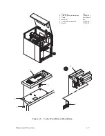
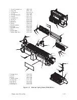
1. Position the ribbon control PCBA in the ribbon deck housing.
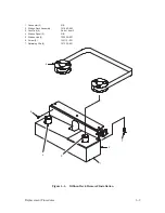
2. Mount the PCBA to the ribbon deck housing with the four hex screws
(17) and flat washers (18).
3. Attach connectors J30 and J33 to the ribbon deck housing.
4. Attach connectors (11) and (12) to PCBA connectors RMJ2 and RGJ2.
5. Attach connectors (7) and (8) to PCBA connectors RMJ1 and RGJ1.
6. Attach connector J45 to shunt plug P45.
7. Position the ribbon deck covers on the ribbon deck housing.
8. Install two screws (1) and washers (2).
9. Install the ribbon deck assembly as described on page 6–8.
Содержание P9012
Страница 1: ...P N 132305 001 Rev E P9012 Multifunction Line Printer...
Страница 49: ...2 31 Principles of Operation Power Supply PCBAs 1 3 SHORT OPEN Figure 2 21 Power Supply PCBA...
Страница 53: ...2 35 Principles of Operation PAPER FEED MOTOR TRACTORS PAPER TRANSPORT Figure 2 26 Paper Feed Components...
Страница 58: ...2 40 Principles of Operation...
Страница 84: ...4 18 Troubleshooting...
Страница 107: ...5 23 Alignments and Adjustments 1 Screw 2 MPU Arm 1 2 Figure 5 9 Magnetic Pickup Phasing Adjustment...
Страница 118: ...5 34 Alignments and Adjustments...
Страница 203: ...6 85 Replacement Procedures This page intentionally left blank...
Страница 214: ...6 96 Replacement Procedures...
Страница 217: ...A 3 Power Paper Stacker Maintenance Printer Rear Power Paper Stacker Figure A 1 Power Paper Stacker...
Страница 236: ...A 22 Power Paper Stacker Maintenance...
Страница 246: ...D 2 Torque Table...
Страница 254: ...Index 6...
Страница 255: ......
Страница 256: ...132305 001 Rev E...


