2–25
Principles of Operation
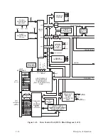
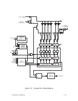
Hammer Driver PCBA
(Figure 2–18 and Figure 2–19)
Each of the print hammers is controlled by electromagnetic coils, a driver,
and a logic circuit which, among other functions, controls the energizing of
the coils.
The hammer logic circuits perform the following functions:
•
Convert serial data bits on the COM line into parallel data bits.
•
Control the energizing of hammer coils to print dots in accordance with
the parallel data.
•
Provide safety features to prevent coils from energizing under conditions
that could damage coils and hammer drivers.
•
Provide an isolated and reg5 VDC supply, 5HL, for TTL logic
on the hammer driver PCBA.
Following a SYNC pulse, hammer shift clock (NHSC) pulses load data from
the COM DATA line into the hammer driver shift register. Every bit on the
COM line is clocked into the shift register by the rising edge of NHSC,
containing dot information for the characters to be printed by each hammer.
After the last bit is clocked into the shift register, the next SYNC pulse
causes hammer clock, NHCK, to load the contents of the shift register into
the data latches.
When a dot is to be printed, the data latch for that hammer is set and the
corresponding Darlington driver transistor is forward biased. At the same
time, the overdrive transistor is also forward biased for a period of time
controlled by the upper drive (NUD) signal from the MCU. During the
overdrive period, 48 volts are placed across the coils whose Darlingtons are
energized. After the NUD period is over, a –12V to ground current path
provides the current for the remainder of the hammers on time. This process
energizes the coil, releasing the hammer to print out.
Hammer reset signal, HRS, resets the output enable (OE) of the latch. The
latch output disables all Darlington drivers and deenergizes the coils. The
rebounding hammers are recaptured by the permanent magnet.
Содержание P9012
Страница 1: ...P N 132305 001 Rev E P9012 Multifunction Line Printer...
Страница 49: ...2 31 Principles of Operation Power Supply PCBAs 1 3 SHORT OPEN Figure 2 21 Power Supply PCBA...
Страница 53: ...2 35 Principles of Operation PAPER FEED MOTOR TRACTORS PAPER TRANSPORT Figure 2 26 Paper Feed Components...
Страница 58: ...2 40 Principles of Operation...
Страница 84: ...4 18 Troubleshooting...
Страница 107: ...5 23 Alignments and Adjustments 1 Screw 2 MPU Arm 1 2 Figure 5 9 Magnetic Pickup Phasing Adjustment...
Страница 118: ...5 34 Alignments and Adjustments...
Страница 203: ...6 85 Replacement Procedures This page intentionally left blank...
Страница 214: ...6 96 Replacement Procedures...
Страница 217: ...A 3 Power Paper Stacker Maintenance Printer Rear Power Paper Stacker Figure A 1 Power Paper Stacker...
Страница 236: ...A 22 Power Paper Stacker Maintenance...
Страница 246: ...D 2 Torque Table...
Страница 254: ...Index 6...
Страница 255: ......
Страница 256: ...132305 001 Rev E...


