2–14
Principles of Operation
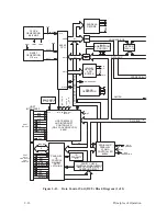
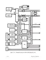
Data Control Unit (DCU) PCBA
(Figure 2–12 and Figure 2–13)
The data control unit (DCU) PCBA begins the printing process by receiving
data through the host interface (J1, J2). Three interfaces are available on the
DCU card: the Centronics and Dataproducts parallel interfaces (J2), and an
RS–232 compatible serial interface (J1) running up to l9,200 baud. Protocols
are set up through the control panel.
In the parallel mode the input data is transferred directly via Direct Memory
Access (DMA) into memory. While in the serial mode, the input data is
entered into the input buffer with an interrupt–driven software routine. Once
the data is in the input buffer, as defined by software, the data is then taken
from the ASCII format to the format used in the dot image buffer (DIB).
Software determines the special character attributes and any special handling
of the data in the DIB due to the control characters.
The data is then loaded to the hammer driver card through the hammer load
circuit. The hammer load circuit is activated by the mechanism control unit
(MCU) pulling the NLOAD signal low. This signal interrupts the processor
at the highest level available. In this case the DCU is a slave to the MCU.
Control of the data transferred to the hammer drivers is done in the DCU. A
signal, NHMRBLK (hammer bank), loads all 0’s or non–printables to the
hammer driver card if asserted when the hammer load circuit is activated.
The DCU commands the MCU to drive all of the motors and other
mechanical interfaces. Print densities are transmitted to the MCU from the
DCU for proper MCU control of the mechanics.
Содержание P9012
Страница 1: ...P N 132305 001 Rev E P9012 Multifunction Line Printer...
Страница 49: ...2 31 Principles of Operation Power Supply PCBAs 1 3 SHORT OPEN Figure 2 21 Power Supply PCBA...
Страница 53: ...2 35 Principles of Operation PAPER FEED MOTOR TRACTORS PAPER TRANSPORT Figure 2 26 Paper Feed Components...
Страница 58: ...2 40 Principles of Operation...
Страница 84: ...4 18 Troubleshooting...
Страница 107: ...5 23 Alignments and Adjustments 1 Screw 2 MPU Arm 1 2 Figure 5 9 Magnetic Pickup Phasing Adjustment...
Страница 118: ...5 34 Alignments and Adjustments...
Страница 203: ...6 85 Replacement Procedures This page intentionally left blank...
Страница 214: ...6 96 Replacement Procedures...
Страница 217: ...A 3 Power Paper Stacker Maintenance Printer Rear Power Paper Stacker Figure A 1 Power Paper Stacker...
Страница 236: ...A 22 Power Paper Stacker Maintenance...
Страница 246: ...D 2 Torque Table...
Страница 254: ...Index 6...
Страница 255: ......
Страница 256: ...132305 001 Rev E...


