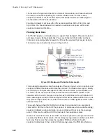
2-14
Chapter 2: Planning Your ITS Deployment
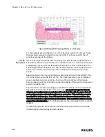
Planning the Sync Network Layout
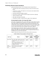
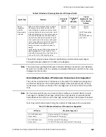
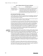
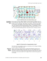
Design of a “Sync Network” is required for any site using more than one Sync Unit. A
site may need more than one Sync Unit if:
• more than 12 APs are needed, or
• if the geographical dispersion and/or location of available equipment closets
dictate this.
The Sync Network is imperative to ensure that all RF channels are driven in
Synchronization and no “drifting” occurs. While these connections are made using
UTP/CAT5 (or greater) cabling like the other network connections, these are non-
data connections that be run up to 500 meters (1640 feet). Note that even ITSs that
support non-contiguous RF coverage areas must be synchronized if they are located
at the same hospital site. See Appendix A, “Installing Multiple ITSs at a Single
Hospital Site” for details and requirements.
A Sync Unit can support up to 12 APs and can be configured as a Master or a Slave
using its front-panel. It is also possible for a Sync Unit to act as a Master to feed up
to 13 Slave Sync Units.The Master Sync Unit is the unit at the head of the chain, or
center of the topology and is used to generate the synchronization signal format to
other (slave) Sync Units. Slave Units act as regenerators to further distribute the
signal if needed.
Note that there must be only one Sync Unit designated as a Master, all others must
be Slaves. Also, note that an Access Point cannot be operated from the ‘TO SLAVE
SU’ output on the Sync Unit. APs should only be connected to an “AP/SU” port that
sources sync signal, power, and data.
The maximum number of Sync Units that may be linked in a single daisy-chain is 4
(including the Master Sync Unit). Larger installations requiring a Star topology
typically have the Master Sync Unit located in the middle. Arms of the Star may each
have chains of up to four Sync Units total.
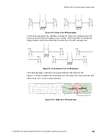
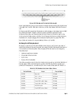
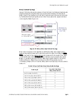
There are three main Sync network topologies:
• Daisy-chained topology
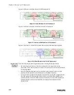
• Star Topology
• Hybrid Topology
862164
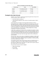
Cisco 3550 Router: Fiber
85 Watts
862247
Cisco 3560-24TS Router
45 Watts
862248
Cisco 3750-24FS Router
70 Watts
862147
APC 10
Watts
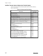
Table 2-4: ITS Infrastructure Device Power Draws
Product Number
Device
Power in Watts
Содержание IntelliVue Telemetry System Infrastructure
Страница 8: ...viii Contents ...
Страница 14: ...xiv About This Guide ...
Страница 100: ...3 22 Chapter 3 Installing and Configuring the ITS Figure 3 10 APC Filter Configuration Screen ...
Страница 102: ...3 24 Chapter 3 Installing and Configuring the ITS Figure 3 11 BOOTP DHCP Server Configuration Screen ...
Страница 162: ...5 12 Chapter 5 Troubleshooting and Testing ...
Страница 168: ...A 6 Chapter A Installing Multiple ITSs at a Single Hospital Site ...
Страница 180: ...Index 8 Index ...

