PART 1: CX-Programmer
OMRON
CHAPTER 2 – Quick Start Guide
CX-Programmer _Page 25
Comment view must be explicitly selected to be displayed. All views can be opened at the same time and can be
selected via options associated with the
Window
menu.
The Ladder program graphically represents the PLC power flow from left to right and the program sequence
from top to bottom.
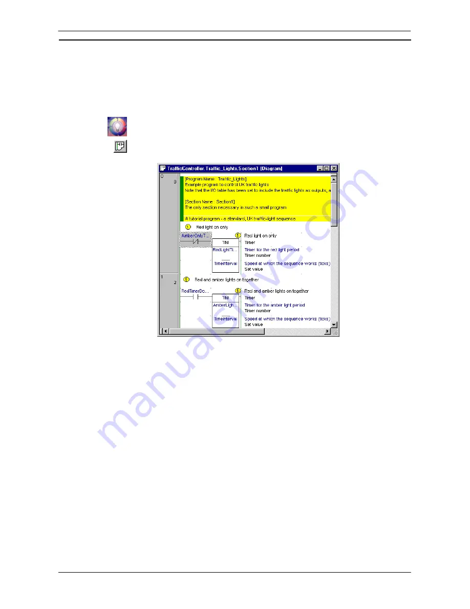
PLC program instructions can be entered as a graphical representation in Ladder form. Programs can be created,
edited and monitored in this view.
Follow the examples provided to develop an understanding of the Diagram Workspace.
Select the
View Diagram
button from the toolbar. The Ladder program window is displayed
in the Diagram Workspace.
The following items are standard features of the Ladder program area:
♦
Cursor
. A rectangular block showing the current position within the rung. The location of the cursor is
displayed in the status bar.
♦
Rung
. A logical unit of a ladder program. A rung can encompass one or more rows and columns. All rungs
are numbered.
♦
Bus-bars
. The left bus-bar provides a graphical representation of the power supply bus-bar. The right bus-
bar contains the output region: to align objects to the right bus-bar. The right bus-bar is selectable for
display. If shown, the ladder rungs are justified so that the outputs of the rungs are organized along it.
♦
Grid Dots
. Dots that display at the connection points of each cell. To display the grid, select the
Grid
button from the toolbar.
♦
Rung Margin Area
. The area to the left of the Left bus-bar. The rung number and step number for each rung
are shown here (rung number on the left).
♦
Automatic Error Detection
. A bar is displayed to the left of the currently selected rung area. As elements
and instructions are added to the rung, the additions are automatically checked to see if they are valid. The
color of the bar indicates the validity of the program: red highlights an error, whilst green indicates a correct
entry. In addition, elements of the text on the ladder are drawn in this error color if a problem exists.
The color and display preferences of the above features can be amended by selecting
Options
from the
Tools
menu.
More than one element in a rung can be selected by pressing the mouse button down on an element and, keeping
the left-mouse button depressed, dragging a highlight over other elements in the rung. Selected elements can
then be moved as a block.
Содержание CX-Programmer 9
Страница 1: ...Cat No W446 E1 10 CX Programmer Ver 9 SYSMAC WS02 CXPC_ V9 OPERATION MANUAL...
Страница 2: ......
Страница 3: ...SYSMAC WS02 CXPC V9 CX Programmer Ver 9 Operation Manual Revised December 2009...
Страница 4: ......
Страница 6: ......
Страница 19: ...CX Programmer_Page xvi Unit Versions and Lot Numbers...
Страница 30: ......
Страница 31: ...PART 1 CX Programmer...
Страница 32: ......
Страница 100: ......
Страница 120: ......
Страница 198: ...PART 1 CX Programmer CHAPTER 4 Reference OMRON CX Programmer _Page 118...
Страница 224: ...PART 1 CX Programmer Keyboard Shortcuts CX Programmer OMRON CX Programmer _Page 144...
Страница 240: ......
Страница 241: ...PART 2 CX Server PLC Tools...
Страница 242: ......
Страница 250: ......
Страница 256: ......
Страница 268: ...PART 2 CX Server PLC Tools CHAPTER 2 PLC Memory Component OMRON CX Server PLC Tools_Page 18...
Страница 286: ......
Страница 338: ......
Страница 382: ......
Страница 414: ......
Страница 430: ......
Страница 436: ......
Страница 437: ...PART 3 CX Server Runtime...
Страница 438: ......
Страница 482: ......
Страница 488: ......
Страница 504: ......
Страница 530: ......
Страница 540: ......
Страница 541: ......
Страница 542: ......


