


38
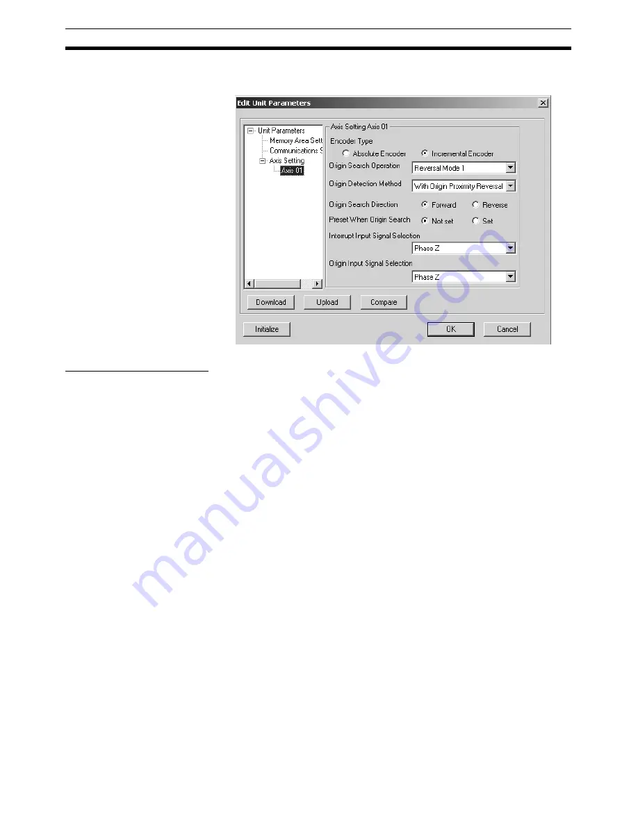
Editing Unit Parameters
Section 5-1
2.
Select
Axis
@@
, where
@@
is the number of the axis to be edited (
@@
: 01
to 16).
Editing Axis Parameters
1,2,3...
1.
Select the Encoder Type.
Select from either
Absolute Encoder
or
Incremental Encoder.
2.
Set the Origin Search Operation.
Select one of the following:
Reversal Mode 1, Reversal Mode 2, Single-direction Mode, or Reversal
Mode 3.
3.
Set the Origin Detection Method.
Select either
With Origin Proximity Reversal, No Origin Proximity Reversal,
or Not Use Origin Proximity
.
4.
Set the Origin Search Direction.
Select either
Forward
or
Reverse
.
5.
Set the Preset When Origin Search.
Select either
Not Set
or
Set
.
6.
Select the Interrupt Input Signal.
Click the drop-down list and select a signal used as the Interrupt Input Sig-
nal.
7.
Select the Origin Input Signal.
Click the drop-down list and select a signal used as the Origin Input Signal.
Note
(1) Make sure that the same direction is set for Origin Search Direction in the
Axis Parameters and Zero Point Return Direction in the Servo Parame-
ters. Setting different directions may result in a malfunction. (The Origin
Search Direction parameters are as follows: W Series (with and without
built-in communications) and SMARTSTEP Junior (with built-in commu-
nications): Pn816.0, G Series (with built-in communications): Pn204.)
(2) When using an absolute encoder, make sure that the settings for the En-
coder Type in the Axis Parameters and Operation Switch when Using Ab-
solute Encoder in the Servo Parameters match. If the settings do not
match, ORIGIN SEARCH execution will not be possible, or another mal-
Содержание CX-MOTION-NCF - V1.8
Страница 2: ...CXONE AL C V3 CXONE AL D V3 CX Motion NCF Ver 1 8 Operation Manual Revised October 2008...
Страница 3: ...iv...
Страница 5: ...vi...
Страница 21: ...xxii Application Precautions 5...
Страница 33: ...12 Connecting to PLC Section 2 2...
Страница 36: ...15 Screen Name Section 3 1 Edit Parameter Windows...
Страница 37: ...16 Screen Name Section 3 1 Monitor Windows Axis Monitor Window Unit Monitor Window...
Страница 63: ...42 Editing Servo Parameters Section 5 2...
Страница 68: ...47 Print Section 6 5 Print Samples An example of printed Unit Parameters is shown below...
Страница 89: ...68 Writing to Flash Memory Section 7 6...
Страница 95: ...74 Axis Monitor Section 8 2 2 Click the OK Button to start communications i e establish connection...
Страница 103: ...82 Axis Monitor Section 8 2...
Страница 104: ...83 SECTION 9 Test Run Operation This section describes the test run operations for each axis 9 1 Test Run 84...
Страница 109: ...88 Test Run Section 9 1...
Страница 133: ...112 Index...
Страница 137: ...116 Revision History...


