4-3 Manually
Setting Data Links
4-3-4 Creating
Data
Link Tables Offline
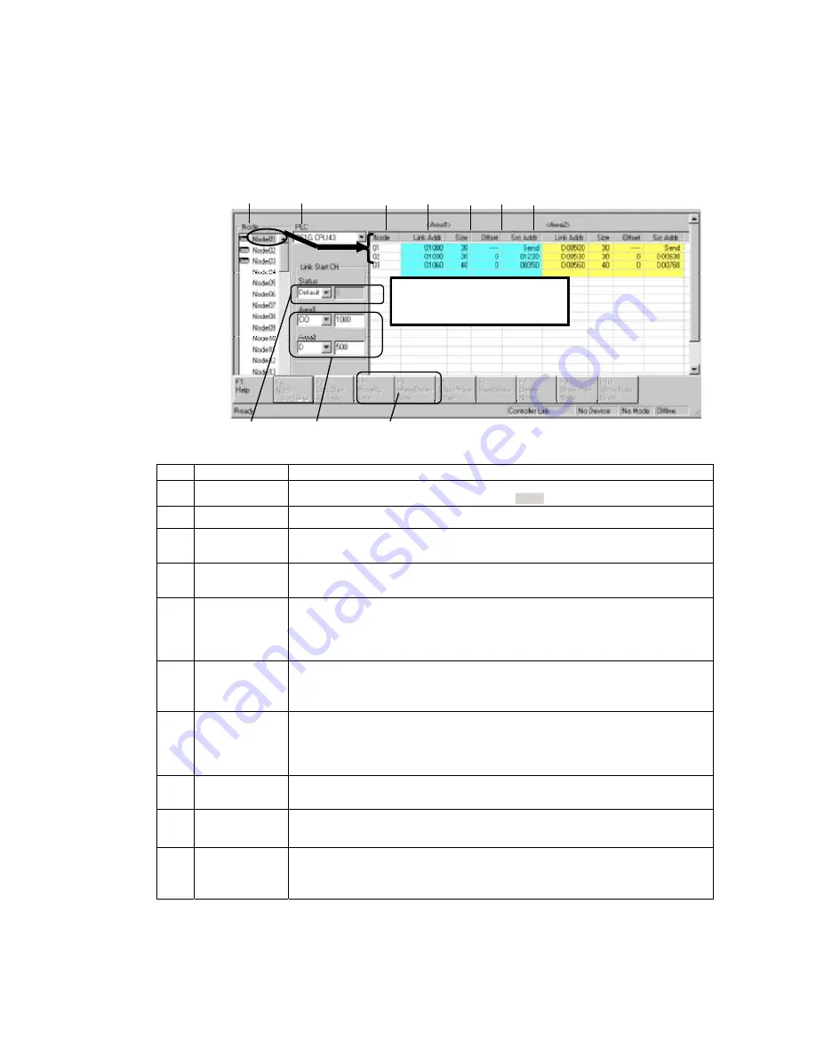
Node Editing Window Settings
Set the data link details for each node (i.e., send size, receive size, reception offset) in
the Node Editing Window.
Note: The Node Edit Window appears in table format by default, as shown below. To convert it
back into the earlier list format, select
View - Show in List
.
The settings for each active node
shown in the node field to the left are
displayed here.
(1)
(2)
(5)
(6)
(7)
(8)
(9)
(3)
(4)
(10)
No. Name
Description
(1)
Node
Selects the address of the node to be edited.
The settings for an active node (selected with
) are displayed to the right.
(2)
PLC
The PLC type set by the Datalink Wizard is displayed and can be changed here.
(3)
Status
The status memory area and start address set by the Datalink Wizard are displayed
and can be changed here.
(4)
Area 1/Area 2
The Area 1 and Area 2 classifications and start addresses set by the Datalink Wizard
are displayed and can be changed here.
(5) Node
(Display only.
Order can be
changed.)
•
Node addresses are displayed from top to bottom, in order of node refreshing at the
local node (in order of allocated node address).
•
To change the refresh sequence set by the Datalink Wizard, click either F4: Move Up
Area or F5: Move Down Area in the Function Bar, or press the corresponding
Function key.
(6) Link
Addr.
(Automatic
display)
•
For the local node send area, the start address of the data sent from the local node is
automatically displayed.
•
For the receive area from remote nodes, the local node start address for storing data
received from remote nodes is automatically displayed.
(7) Size
(Setting/Display)
•
For the local node send area, the send size set by the Datalink Wizard is displayed
and can be changed here.
•
For the receive area from remote nodes, the receive size from remote nodes is set
here in word units. (It can only be set here.) The default is the entire send size from
remote nodes.
(8) Offset
(Setting/Display)
The reception offset from the source start address displayed at “Src. Addr.” is set here.
(The default is 0.)
(9) Src.
Addr.
(Automatic
display)
•
For the local node send area, “Send” is automatically displayed.
•
For the receive area from a remote node, the remote node’s source start address (the
value before the offset) is automatically displayed.
(10)
F4: Move Up
Area
F5: Move Down
Area
Changes the node refresh sequence.
Note: The areas and start addresses that can be set for Controller Link data link status depend on the
model of CPU Unit. If the start address is not set correctly, a data link table error will occur and
the LNK indicator on the Controller Link Unit will flash. Refer to the
Controller Link Unit
Operation Manual
for details.
4-18
Содержание CX-INTEGRATOR - V1.1
Страница 1: ...OPERATION MANUAL CX Integrator Ver 1 1 SYSMAC CXONE AL C E Cat No W445 E1 02...
Страница 2: ...CXONE AL C E CX Integrator Ver 1 1 Operation Manual Revised November 2005...
Страница 3: ...iv...
Страница 5: ...vi...
Страница 13: ...xiv...
Страница 120: ...Communications Section 3 Routing Tables This section describes how to set the routing tables 3...
Страница 200: ...Communications Section 5 Ethernet This section describes the operations specific to Ethernet 5...
Страница 292: ...Communications Section 8 NT Links This section explains the settings and operations specific to the NT Link system 8...
Страница 328: ...Appendices A...
Страница 336: ......


