


USBx_INTEN field descriptions (continued)
Field
Description
1
ERROREN
ERROR Interrupt Enable
0
Disables the ERROR interrupt.
1
Enables the ERROR interrupt.
0
USBRSTEN
USBRST Interrupt Enable
0
Disables the USBRST interrupt.
1
Enables the USBRST interrupt.
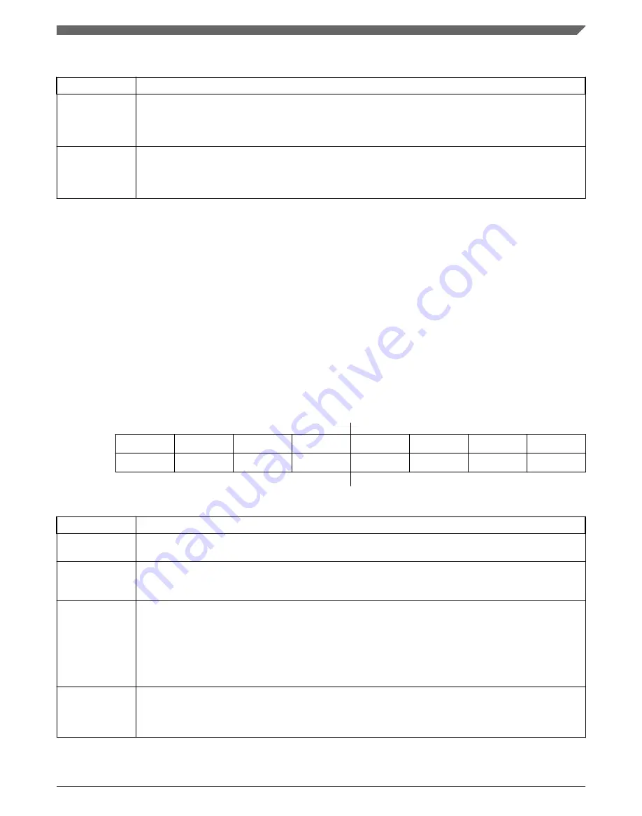
51.4.11 Error Interrupt Status register (USBx_ERRSTAT)
Contains enable bits for each of the error sources within the USB Module. Each of these
bits are qualified with their respective error enable bits. All bits of this register are
logically OR'd together and the result placed in the ERROR bit of the ISTAT register.
After an interrupt bit has been set it may only be cleared by writing a one to the
respective interrupt bit. Each bit is set as soon as the error condition is detected.
Therefore, the interrupt does not typically correspond with the end of a token being
processed. This register contains the value of 0x00 after a reset.
Address: 4005_5000h base + 88h offset = 4005_5088h
Bit
7
6
5
4
3
2
1
0
Read
Write
Reset
0
0
0
0
0
0
0
0
USBx_ERRSTAT field descriptions
Field
Description
7
BTSERR
This bit is set when a bit stuff error is detected. If set, the corresponding packet is rejected due to the error.
6
OWNERR
This field is valid when the USB Module is operating in peripheral mode (CTL[HOSTMODEEN]=0). It is set
if the USB Module requires a new BD for SETUP, ISO IN, or ISO OUT transfer while a new BD is not
available.
5
DMAERR
This bit is set if the USB Module has requested a DMA access to read a new BDT but has not been given
the bus before it needs to receive or transmit data. If processing a TX transfer this would cause a transmit
data underflow condition. If processing a RX transfer this would cause a receive data overflow condition.
This interrupt is useful when developing device arbitration hardware for the microprocessor and the USB
module to minimize bus request and bus grant latency. This bit is also set if a data packet to or from the
host is larger than the buffer size allocated in the BDT. In this case the data packet is truncated as it is put
in buffer memory.
4
BTOERR
This bit is set when a bus turnaround timeout error occurs. The USB module contains a bus turnaround
timer that keeps track of the amount of time elapsed between the token and data phases of a SETUP or
OUT TOKEN or the data and handshake phases of a IN TOKEN. If more than 16 bit times are counted
from the previous EOP before a transition from IDLE, a bus turnaround timeout error occurs.
Table continues on the next page...
Chapter 51 Universal Serial Bus Full Speed OTG Controller (USBFSOTG)
K32 L2A Reference Manual, Rev. 2, 01/2020
NXP Semiconductors
1315
Содержание K32 L2A Series
Страница 2: ...K32 L2A Reference Manual Rev 2 01 2020 2 NXP Semiconductors...
Страница 42: ...K32 L2A Reference Manual Rev 2 01 2020 42 NXP Semiconductors...
Страница 122: ...Flash Memory Clock K32 L2A Reference Manual Rev 2 01 2020 122 NXP Semiconductors...
Страница 146: ...Module operation in low power modes K32 L2A Reference Manual Rev 2 01 2020 146 NXP Semiconductors...
Страница 158: ...Debug and security K32 L2A Reference Manual Rev 2 01 2020 158 NXP Semiconductors...
Страница 174: ...Module Signal Description Tables K32 L2A Reference Manual Rev 2 01 2020 174 NXP Semiconductors...
Страница 246: ...Application information K32 L2A Reference Manual Rev 2 01 2020 246 NXP Semiconductors...
Страница 322: ...Kinetis Bootloader Status Error Codes K32 L2A Reference Manual Rev 2 01 2020 322 NXP Semiconductors...
Страница 344: ...Application initialization information K32 L2A Reference Manual Rev 2 01 2020 344 NXP Semiconductors...
Страница 374: ...CMP Trigger Mode K32 L2A Reference Manual Rev 2 01 2020 374 NXP Semiconductors...
Страница 384: ...Functional description K32 L2A Reference Manual Rev 2 01 2020 384 NXP Semiconductors...
Страница 592: ...Application Information K32 L2A Reference Manual Rev 2 01 2020 592 NXP Semiconductors...
Страница 602: ...Initialization and application information K32 L2A Reference Manual Rev 2 01 2020 602 NXP Semiconductors...
Страница 656: ...Functional Description K32 L2A Reference Manual Rev 2 01 2020 656 NXP Semiconductors...
Страница 664: ...Functional Description K32 L2A Reference Manual Rev 2 01 2020 664 NXP Semiconductors...
Страница 744: ...Functional description K32 L2A Reference Manual Rev 2 01 2020 744 NXP Semiconductors...
Страница 762: ...Functional description K32 L2A Reference Manual Rev 2 01 2020 762 NXP Semiconductors...
Страница 806: ...Functional description K32 L2A Reference Manual Rev 2 01 2020 806 NXP Semiconductors...
Страница 868: ...Integer square root K32 L2A Reference Manual Rev 2 01 2020 868 NXP Semiconductors...
Страница 976: ...Functional description K32 L2A Reference Manual Rev 2 01 2020 976 NXP Semiconductors...
Страница 1012: ...Functional description K32 L2A Reference Manual Rev 2 01 2020 1012 NXP Semiconductors...
Страница 1094: ...Functional description K32 L2A Reference Manual Rev 2 01 2020 1094 NXP Semiconductors...
Страница 1132: ...Functional description K32 L2A Reference Manual Rev 2 01 2020 1132 NXP Semiconductors...
Страница 1182: ...Functional description K32 L2A Reference Manual Rev 2 01 2020 1182 NXP Semiconductors...
Страница 1290: ...Functional description K32 L2A Reference Manual Rev 2 01 2020 1290 NXP Semiconductors...
Страница 1344: ...USB Voltage Regulator Module Signal Descriptions K32 L2A Reference Manual Rev 2 01 2020 1344 NXP Semiconductors...
Страница 1356: ...Initialization Application Information K32 L2A Reference Manual Rev 2 01 2020 1356 NXP Semiconductors...