46
EN
M1.1.TZHD30S-50S.NLFREN - 15032019
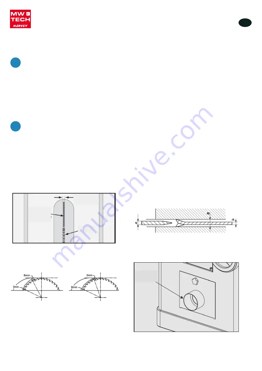
D. Place a straightedge against the blade and the
spreader. When properly aligned, the
spreader/riving knife will be in the "alignment
zone," shown in
Fig.16
, and will be parallel with the
blade.
Fig.16 alignment zone
After changing a saw blade, always check that the
Riving knife or Blade Guard is correctly set!
A. Riving knives shall be manufactured from steel
with an ultimate tensile strength of 580 N mm-2 or
of a comparable material, have flat sides (within
0,1 mm per 100 mm) and shall have a thickness
less than the width of cut (kerf) and at least 0,2mm
greater than the saw blade plate. As
Fig.17
Fig.17
Key:
e riving knife thickness
b saw blade blade
B kerf(width of saw blade cut)
B. The distance of the riving knife from the gear rim
must be between 3mm and 8mm. measured
radially through the centre of the saw spindle. As
Fig.18
Fig.18
C. The highest point of the riving knife must be set
beneath the topmost teeth.
5.4.9 Extraction system
Dust collector device should be prepared by
customer.
The dust extraction equipment is to be
switched on before commencing machining.
The outlet diameter is 100mm.
Fig.19
Air current speed is 20m/s for vacuum suction dust
emission index, when air current speed of dust
collector device (in accordance with EN
12779:2004) is not lower than 20m/s, ensure
machine can be normal exhausted.
1. Required air flow: 800 m3/h;
2. Ensure pressure drop of each dust collector
outlet carrying air current speed: 1100Pa
3. Dry chips: 20m/s.
4. Wet chips: 28m/s. (water content is equal
to18%)
Fig.19
Figure 17
D. Place a straightedge against the blade and the
spreader. When properly aligned, the
spreader/riving knife will be in the "alignment
zone," shown in
Fig.16
, and will be parallel with the
blade.
Fig.16 alignment zone
After changing a saw blade, always check that the
Riving knife or Blade Guard is correctly set!
A. Riving knives shall be manufactured from steel
with an ultimate tensile strength of 580 N mm-2 or
of a comparable material, have flat sides (within
0,1 mm per 100 mm) and shall have a thickness
less than the width of cut (kerf) and at least 0,2mm
greater than the saw blade plate. As
Fig.17
Fig.17
Key:
e riving knife thickness
b saw blade blade
B kerf(width of saw blade cut)
B. The distance of the riving knife from the gear rim
must be between 3mm and 8mm. measured
radially through the centre of the saw spindle. As
Fig.18
Fig.18
C. The highest point of the riving knife must be set
beneath the topmost teeth.
5.4.9 Extraction system
Dust collector device should be prepared by
customer.
The dust extraction equipment is to be
switched on before commencing machining.
The outlet diameter is 100mm.
Fig.19
Air current speed is 20m/s for vacuum suction dust
emission index, when air current speed of dust
collector device (in accordance with EN
12779:2004) is not lower than 20m/s, ensure
machine can be normal exhausted.
1. Required air flow: 800 m3/h;
2. Ensure pressure drop of each dust collector
outlet carrying air current speed: 1100Pa
3. Dry chips: 20m/s.
4. Wet chips: 28m/s. (water content is equal
to18%)
Fig.19
Figure 18
4. Place a straightedge against the blade and the spreader. When properly aligned, the spreader/riving knife will be in the
alignment zone, shown in figure 16, and will be parallel with the blade.
NOTICE
After changing a saw blade, always check that the riving knife or blade guard is correctly set!
1. Riving knives shall be manufactured from steel with an ultimate tensile strength of 580 N/mm² or of a comparable material,
have flat sides (within 0.1 mm per 100 mm) and shall have a thickness less than the width of cut (kerf) and at least 0.2 mm
greater than the saw blade plate (figure 17).
2. The distance of the riving knife from the gear rim must be between 3 mm and 8 mm measured radially through the centre of
the saw spindle (figure 18).
3. The highest point of the riving knife must be set beneath the topmost teeth.
Extraction system
NOTICE
Dust collector device should be prepared by customer�
The dust extraction equipment is to be switched on before commencing machining�
The outlet diameter is 100 mm (figure 19).
Air current speed is 20 m/s for vacuum suction dust emission index. When air current speed of dust collector device (in
accordance with EN 12779:2004) is not lower than 20 m/s, ensure machine can be normal exhausted.
1.
Required air flow: 800 m³/h.
2. Ensure pressure drop of each dust collector outlet carrying air current speed: 1100 Pa
3. Dry chips: 20 m/s
4. Wet chips: 28 m/s (water content is equal to 18%)
!
!
D. Place a straightedge against the blade and the
spreader. When properly aligned, the
spreader/riving knife will be in the "alignment
zone," shown in
Fig.16
, and will be parallel with the
blade.
Fig.16 alignment zone
After changing a saw blade, always check that the
Riving knife or Blade Guard is correctly set!
A. Riving knives shall be manufactured from steel
with an ultimate tensile strength of 580 N mm-2 or
of a comparable material, have flat sides (within
0,1 mm per 100 mm) and shall have a thickness
less than the width of cut (kerf) and at least 0,2mm
greater than the saw blade plate. As
Fig.17
Fig.17
Key:
e riving knife thickness
b saw blade blade
B kerf(width of saw blade cut)
B. The distance of the riving knife from the gear rim
must be between 3mm and 8mm. measured
radially through the centre of the saw spindle. As
Fig.18
Fig.18
C. The highest point of the riving knife must be set
beneath the topmost teeth.
5.4.9 Extraction system
Dust collector device should be prepared by
customer.
The dust extraction equipment is to be
switched on before commencing machining.
The outlet diameter is 100mm.
Fig.19
Air current speed is 20m/s for vacuum suction dust
emission index, when air current speed of dust
collector device (in accordance with EN
12779:2004) is not lower than 20m/s, ensure
machine can be normal exhausted.
1. Required air flow: 800 m3/h;
2. Ensure pressure drop of each dust collector
outlet carrying air current speed: 1100Pa
3. Dry chips: 20m/s.
4. Wet chips: 28m/s. (water content is equal
to18%)
Fig.19
Figure 16 Alignment zone
Blade
Spreader or
riving knife
Alignment
zone
D. Place a straightedge against the blade and the
spreader. When properly aligned, the
spreader/riving knife will be in the "alignment
zone," shown in
Fig.16
, and will be parallel with the
blade.
Fig.16 alignment zone
After changing a saw blade, always check that the
Riving knife or Blade Guard is correctly set!
A. Riving knives shall be manufactured from steel
with an ultimate tensile strength of 580 N mm-2 or
of a comparable material, have flat sides (within
0,1 mm per 100 mm) and shall have a thickness
less than the width of cut (kerf) and at least 0,2mm
greater than the saw blade plate. As
Fig.17
Fig.17
Key:
e riving knife thickness
b saw blade blade
B kerf(width of saw blade cut)
B. The distance of the riving knife from the gear rim
must be between 3mm and 8mm. measured
radially through the centre of the saw spindle. As
Fig.18
Fig.18
C. The highest point of the riving knife must be set
beneath the topmost teeth.
5.4.9 Extraction system
Dust collector device should be prepared by
customer.
The dust extraction equipment is to be
switched on before commencing machining.
The outlet diameter is 100mm.
Fig.19
Air current speed is 20m/s for vacuum suction dust
emission index, when air current speed of dust
collector device (in accordance with EN
12779:2004) is not lower than 20m/s, ensure
machine can be normal exhausted.
1. Required air flow: 800 m3/h;
2. Ensure pressure drop of each dust collector
outlet carrying air current speed: 1100Pa
3. Dry chips: 20m/s.
4. Wet chips: 28m/s. (water content is equal
to18%)
Fig.19
Figure 19
Dust outlet
(100 mm)
copyrighted
document
- all
rights
reserved
by
FBC


