


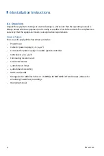


7 Wiring of the Device
40
Rev. 02/2018
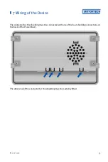
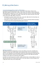
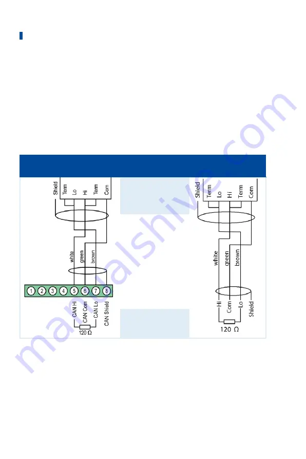
Connection between Ignition Controller and PowerView3
As shown in the following illustrations, you can connect the PowerView3 directly to the
MOTORTECH ignition controller (MIC3, MIC3+, MIC4, MIC4+, MIC5, MIC5+) using the CAN cable
delivered with the PowerView3. To do so, you need to insert the connector into the CAN interface
on the PowerView3. On the ignition controller, connect the color-coded conductors of the CAN
cable to the correct CAN interface connections.
–
With ignition controllers with a service cover, connect the CAN cable of the PowerView3 via
the contacts of the corresponding connector strip.
–
With ignition controllers without a service cover, connect the CAN cable of the PowerView3
via the contacts of the corresponding military style connector.
Ignition controllers
with service cover
Ignition controllers
without service cover
Connector for CAN
interface on
PowerView3
CAN cable
CAN interface on the
ignition controller
Settings on the Devices
All connected devices are designated as nodes on the CAN bus. Each node is identified by a
CANopen
®
-node ID. These node numbers must be indicated both in the connected devices as
well as in the configuration of the PowerView3. Refer to the operating manuals of the respective
devices for instructions on how to set the node ID for each device and to determine if further
settings must be made to communicate via the CAN bus.
A node ID can only be assigned once within a CAN bus and must be a number between 1 and 127.
Note that some devices use several node numbers. The node numbers must be assigned in the
configuration after start-up of the PowerView3.
Содержание PoewerView3
Страница 1: ...PowerView3 HMI Module Operating Manual P N 01 10 015 EN Rev 02 2018...
Страница 16: ...4 Product Description 16 Rev 02 2018...
Страница 17: ...4 Product Description Rev 02 2018 17...
Страница 18: ...4 Product Description 18 Rev 02 2018...
Страница 19: ...4 Product Description Rev 02 2018 19...
Страница 26: ...4 Product Description 26 Rev 02 2018 4 1 8 Overview Drawings Rear View...
Страница 27: ...4 Product Description Rev 02 2018 27 Plan View Side View...
Страница 137: ...Rev 02 2018 137...
Страница 138: ......


