


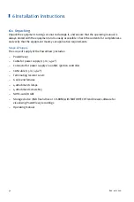


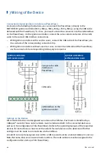


7 Wiring of the Device
38
Rev. 02/2018
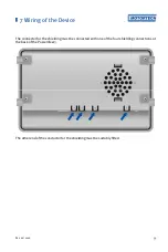
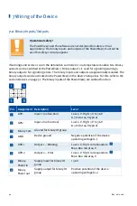
Pin Assignment of the Interface of the CAN Field Bus
Pin
Assignment Description
Com
Common ground for CAN and RS485 group
Term
Bridge with Hi for CAN bus termination
Hi
CAN Hi
Lo
CAN
Lo
Term
Bridge with Lo for CAN bus termination
Pins 6 to 12 are reserved for the RS485 interface and are without function.
CAN bus termination
The PowerView3 has a built-in 120 Ω terminating resistor and must
therefore be the last device in the CAN bus.
If the PowerView3 is not the last device in the CAN bus, the cables of
connection 2 and 5 must be separated.
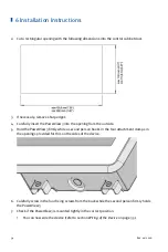
The arrangement of the interfaces of the PowerView3 can be found in the chapter
Interfaces
on
Connection of the CAN Cable
If needed, use the supplied wire end ferrules to connect the strands to clamps. The conductors
of the CAN cable included are assigned as follows:
Color
Assignment
Green
Ground for CAN
(Com)
White CAN
Hi
Brown
CAN Lo
Yellow Not
assigned
Содержание PoewerView3
Страница 1: ...PowerView3 HMI Module Operating Manual P N 01 10 015 EN Rev 02 2018...
Страница 16: ...4 Product Description 16 Rev 02 2018...
Страница 17: ...4 Product Description Rev 02 2018 17...
Страница 18: ...4 Product Description 18 Rev 02 2018...
Страница 19: ...4 Product Description Rev 02 2018 19...
Страница 26: ...4 Product Description 26 Rev 02 2018 4 1 8 Overview Drawings Rear View...
Страница 27: ...4 Product Description Rev 02 2018 27 Plan View Side View...
Страница 137: ...Rev 02 2018 137...
Страница 138: ......


