Appendix 1 Cable
MITSUBISHI CNC
164
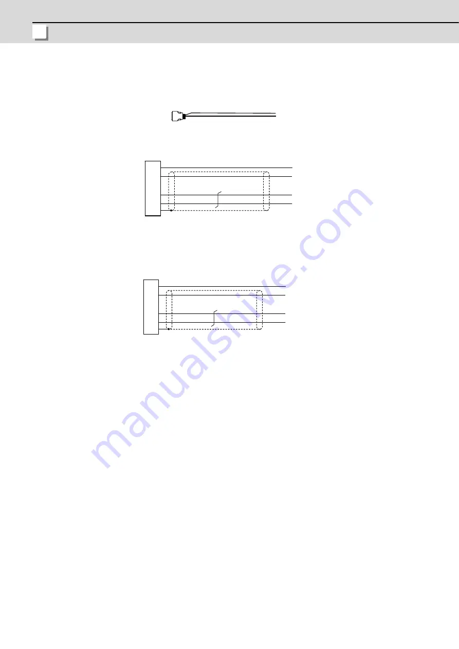
Appendix 1.13 DG24 Cable
Max. cable length: 10m
Application: 5V spply/DO output cable (For drive unit - battery box)
(Note)
The battery box side is connected using a bare conductor or a terminal bar.
<DG24 cable connection diagram (Connection cable for alarm output between drive unit and MDS-BTBOX-36)>
(For MDS-D2/DH2)
<DG24 cable connection diagram (Connection cable for alarm output between drive unit and MDS-BTBOX-36)>
(For MDS-DM2)
20
13
4
1
FG
DICOM
D11
P5
LG
+24V
DO(ALM)
+5V
LG
0.2mm
2
:10120-3000VE
:10320-52F0-008
0.2mm
2
0.2mm
2
Case
grounding
(DC power)
Drive unit side connector
Connector
Shell kit
Battery box side
Blue
Yellow
Light blue
White
20
13
4
1
FG
DICOM
D11
P5
LG
24G
DOCOM
+5V
LG
0.2mm
2
:10120-3000VE
:10320-52F0-008
0.2mm
2
0.2mm
2
Case
grounding
(DC power)
Drive unit side connector
Connector
Shell kit
Battery box side
Blue
Yellow
Light blue
White
Содержание M70V Series
Страница 1: ......
Страница 13: ......
Страница 15: ......
Страница 17: ......
Страница 19: ......
Страница 21: ......
Страница 25: ......
Страница 26: ...1 1 System Configuration ...
Страница 36: ...11 2 General Specifications ...
Страница 110: ...85 3 Installation ...
Страница 120: ...95 4 Connection ...
Страница 173: ...4 Connection MITSUBISHI CNC 148 ...
Страница 174: ...149 付録 Ap 1 章 149 Appendix 1 Cable ...
Страница 220: ...195 付録 Ap 2 章 195 Appendix 2 EMC Installation Guidelines ...
Страница 232: ...207 付録 Ap 3 章 207 Appendix 3 Restrictions for Lithium Batteries ...
Страница 241: ...Appendix 3 Restrictions for Lithium Batteries MITSUBISHI CNC 216 ...
Страница 242: ...217 付録 Ap 4 章 217 Appendix 4 Precautions for Compliance to UL c UL Standards ...
Страница 246: ......
Страница 250: ......


