M70V Series Connection Manual
4.1 Precautions for Wiring
99
4.1.2 Precautions for Using Optical Communication Cable
An optical communication cable is used for communication between the control unit and the drive unit.
Special precautions, differing from the conventional cable, are required when laying and handling the optical
communication cable.
(Note)
If the cable you use is not Mitsubishi's, malfunctions resulted from connection problems or aged deterioration
are not covered under the warranty.
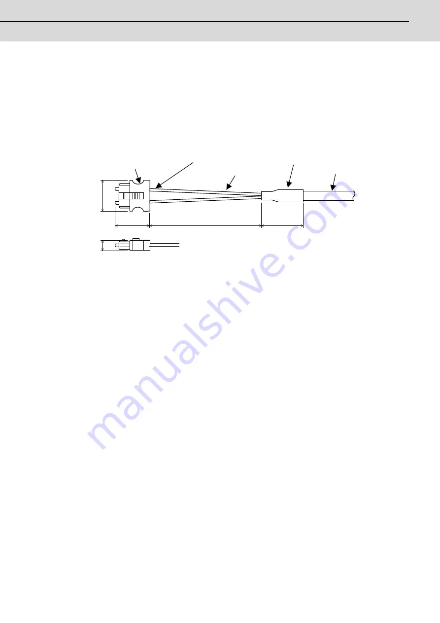
4.1.2.1 Optical Communication Cable Outline and Parts
To ensure the system performance and reliability, purchase the optical communication cable from Mitsubishi. A
machining drawing is given in "Cable" as reference, but the purchased optical communication cable cannot be cut or
connected by the machine tool builder.
4.1.2.2 Precautions for Handling Optical Communication Cable
(1)
A protective cap is attached to the optical module and optical communication cable mounted on the PCB when the
system is delivered. Leaving this protective cap unattached could result in connection faults from the adherence of
dirt and dust. Do not remove the protective cap when not connecting the cable. If dirty, wipe off lightly with a piece
of dry gauze, etc. (Do not use solvents such as alcohol as the optical fiber material could melt.)
(2)
Hold the connector section when connecting or disconnecting the optical connector. Holding the fiber cord will result
in force exceeding the tolerable tension on the fiber cord and connector connection section, and could cause the
fiber cord to dislocate from the optical connector thereby inhibiting use.
(3)
The optical connector cannot be connected in reversed. Check the connector orientation when connecting the
optical communication cable to the optical module. Align the connector lock lever with the lock holes on the PCB's
optical module, and press the connector straight in. Confirm that the lock lever connects with the optical module and
that a "click" is heard.
(4)
When disconnecting the optical communication cable from the PCB, press the lock release buttons on the lock
lever, and pull out the cable while holding the connector section. The connector could be damaged if the cable is
pulled without pressing down on the lock release buttons.
(5)
Do not apply excessive force onto the optical communication cable by stepping on it or dropping tools, etc., on it.
20.3
22.7
150
35
7
Optical connector
Fiber code/connector connection section
Fiber cord
Bushing
Reinforced
sheath
Содержание M70V Series
Страница 1: ......
Страница 13: ......
Страница 15: ......
Страница 17: ......
Страница 19: ......
Страница 21: ......
Страница 25: ......
Страница 26: ...1 1 System Configuration ...
Страница 36: ...11 2 General Specifications ...
Страница 110: ...85 3 Installation ...
Страница 120: ...95 4 Connection ...
Страница 173: ...4 Connection MITSUBISHI CNC 148 ...
Страница 174: ...149 付録 Ap 1 章 149 Appendix 1 Cable ...
Страница 220: ...195 付録 Ap 2 章 195 Appendix 2 EMC Installation Guidelines ...
Страница 232: ...207 付録 Ap 3 章 207 Appendix 3 Restrictions for Lithium Batteries ...
Страница 241: ...Appendix 3 Restrictions for Lithium Batteries MITSUBISHI CNC 216 ...
Страница 242: ...217 付録 Ap 4 章 217 Appendix 4 Precautions for Compliance to UL c UL Standards ...
Страница 246: ......
Страница 250: ......


