M70V Series Connection Manual
2.3 Display Unit
25
2.3 Display Unit
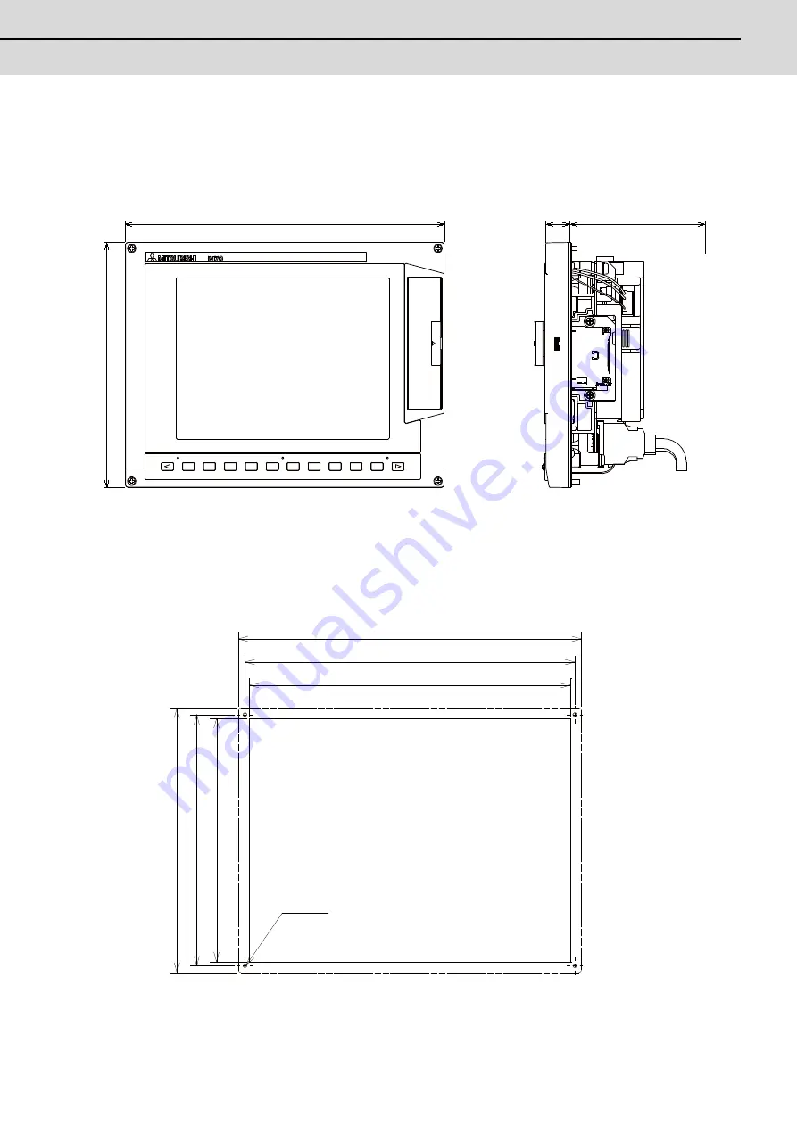
Outline dimension
[FCU7-DU120-12 (8.4-type)]
(Note 1) The above side view shows the state with the control unit mounted.
(Note 2) Consider the minimum radius value of optical communication cable for the bottom space. (Refer to
"Connection : Precautions for Using Optical Communication Cable".)
<Panel cut dimension drawing>
260
200
20 110(
Space required for wiring)
260 (
)
250 ± 0.3
4- M3
200 (
)
190 ±
0
.3
244
184
Unit outline
Unit outline
Screw
(Square hole)
Содержание M70V Series
Страница 1: ......
Страница 13: ......
Страница 15: ......
Страница 17: ......
Страница 19: ......
Страница 21: ......
Страница 25: ......
Страница 26: ...1 1 System Configuration ...
Страница 36: ...11 2 General Specifications ...
Страница 110: ...85 3 Installation ...
Страница 120: ...95 4 Connection ...
Страница 173: ...4 Connection MITSUBISHI CNC 148 ...
Страница 174: ...149 付録 Ap 1 章 149 Appendix 1 Cable ...
Страница 220: ...195 付録 Ap 2 章 195 Appendix 2 EMC Installation Guidelines ...
Страница 232: ...207 付録 Ap 3 章 207 Appendix 3 Restrictions for Lithium Batteries ...
Страница 241: ...Appendix 3 Restrictions for Lithium Batteries MITSUBISHI CNC 216 ...
Страница 242: ...217 付録 Ap 4 章 217 Appendix 4 Precautions for Compliance to UL c UL Standards ...
Страница 246: ......
Страница 250: ......


