background image

iv

Содержание CG-60SR

Страница 1: ...D201611 16 MIMAKI ENGINEERING CO LTD URL http www mimaki co jp...

Страница 2: ...1 3 The Rear 1 3 Operation Panel 1 4 Tray 1 5 Carriage 1 5 Pinch rollers and grit rollers 1 6 Selecting the clamp pressure 1 7 Sheet sensor 1 7 Pen line rubber 1 8 Connecting the cables 1 9 USB Cable...

Страница 3: ...The Flow of Cutting out the Registered Data 3 12 Enter the registration mark detection mode 3 12 Precautions in inputting data with registration marks 3 13 Set for Detecting the Registration Marks 3 1...

Страница 4: ...ther Convenient Settings 3 64 Reset the setting values to the initial state 3 70 CHAPTER 4 In Case of Trouble Before taking a phenomenon as a trouble 4 2 Troubles for which error messages are given on...

Страница 5: ...iv...

Страница 6: ...enerates uses and can radiate radio frequency energy and if not installed and used in accordance with the Operation manual may cause harmful interference to radio communications Operation of this equi...

Страница 7: ...rvice It is also necessary to keep this peration manual on hand Make arrangements to deliver this Operation manual to the person in charge of the operation of this plotter This Operation manual has be...

Страница 8: ...f jam occurrence of a roll sheet Thus the chance of the occurrence of troubles is minimized Two Clamp Pressure Modes Changeover Mechanism The sheet clamp system incorporate two clamp pressure modes ch...

Страница 9: ...bol indicates that it is important to know of the information on proper operation of the plotter Use this information for your operation Indicates the reference page for related contents The symbol in...

Страница 10: ...fire electric shocks or breakdown of the plotter Use of the plotter under an abnormal condition where the device produces smoke or strange smell can result in fire or electric shocks If such an abnorm...

Страница 11: ...printing Heavily curled sheet affects the cutting plotting result Keep your head and hands away from any moving parts during cutting plotting operation otherwise you may get your hair caught in the ma...

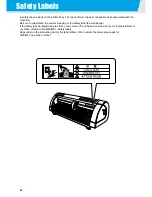
Страница 12: ...to understand the correct meaning of the safety label to avoid danger If the safety label is illegible due to stains or has come off purchase a new one from your local distributor or our office Reorde...

Страница 13: ...anel in addition to the operation procedures Proceed operations confirming them while using This shows the button of the display panel enclose shows the buttons in a sentence This shows the display pa...

Страница 14: ...xiii...

Страница 15: ...on and function 1 3 The Front 1 3 The Rear 1 3 Operation Panel 1 4 Tray 1 5 Carriage 1 5 Pinch rollers and grit rollers 1 6 Selecting the clamp pressure 1 7 Sheet sensor 1 7 Pen line rubber 1 8 Connec...

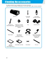
Страница 16: ...er blade for Vinyl Cutter holder Provided withblade Ball point pen Black Marketed item Ball point pen adapter Mounted on the main unit at the factory before shipment Cap Roll placing table Sheet Suppo...

Страница 17: ...ons are set on the operation panel P 1 4 Clamp lever Pushing a lever down lowers a pinch roller and retain the sheet Pinch roller The pinch rollers feed out the sheet while pressing it against the gri...

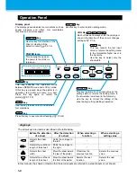
Страница 18: ...alt Press the key again to restart the plotter P 1 10 REMOTE key Use this key to select a tool and establish tool conditions TOOL key Press this key to execute sheet feeding P 3 52 FEED key This key r...

Страница 19: ...t Pointer The light pointer lights up red during positioning for the registration mark detection The light pointer also lights up before detecting the sheet and goes out upon detection of the sheet Ho...

Страница 20: ...h the rotating grit rollers you can injure your fingers with them or your can get your fingers caught between the rotating grit rollers and the platen Be sure to raise the pinch rollers whenever the m...

Страница 21: ...ont and back of the platen one for each Be sure to set the clamps of the left and right to the same mode for use If the clamps modes are different it may cause the sheet misalignment Clamp pressure Ap...

Страница 22: ...n line rubber Pen line rubber is designed 10mm shorter than plotter slot When install the pen line rubber make sure to push it into the slot softly and avoid stretch it forcibly If pen line is stretch...

Страница 23: ...connect the power cable Connect the power cable with the plug outlet of the following power specifications Voltage AC100 240V 10 Frequency 50 60Hz Capacity 145 VA or less Do not plug in or unplug any...

Страница 24: ...essing the key to feed the sheet by the length to be used 6 Pressing the key to make the plotter enter the REMOTE mode REMOTE mode The plotter performs cutting plotting according to the received data...

Страница 25: ...Cutter 2 7 Turning the power on 2 9 Setting the tool conditions 2 10 Kinds of the Tool Conditions 2 10 Set the Tool Conditions 2 11 Loading a sheet of media 2 13 Loading a leaf sheet cut sheet 2 16 Ho...

Страница 26: ...f media 6 Test cutting plotting 7 Cutting plotting See Installing a tool P 2 3 See Mount the Manual Cutter P 2 7 See Turning the power on P 2 9 See Setting the tool conditions P 2 10 See Loading a she...

Страница 27: ...tion Select this to sketch the cutting line Using a cutter How to install a cutter blade 1 Take out the cutter holder 2 Loosen the lock nut and pull the adjusting knob out of the holder 3 Insert the c...

Страница 28: ...cutter blade For reference the protruding amount of the cutter blade 0 3 to 0 5mm Replace the blade when it is blunt Take care not to protrude the blade too much If the cutter is used with its blade...

Страница 29: ...the cutter against the holder 2 Fix the cutter holder Turn the finger grip clockwise and surely fix it Install the cutter to the tool holder of the carriage Be sure to insert the cutter all the way i...

Страница 30: ...the adapter in such a way that the fixing screw will not obstruct operation 6 Turn the knob of the tool holder clockwise to fix the tool When you want to use a commercially available ballpoint pen yo...

Страница 31: ...l the finger grip and hold it up 3 Take out the Cutter blade for manual cutter from accessories and fold the blade with a nipper or the like 4 Set the cutter blade 1 Remove a screw of cutter roller 2...

Страница 32: ...ix the slot of the manual cutter with that of the device 3 Mount the cutter for sure so that you can hear a click sound 6 Paste the arrow sticker on manual cutter cover Paste the arrow sticker accesso...

Страница 33: ...ion fan rotates 3 Check the receiving buffer Then the tool conditions for the currently selected tool appears on the LCD Before turning the power on check that the pinch rollers have been raised Be su...

Страница 34: ...s for performing the dotted cutting You must set the setting of the dotted cutting to ON in advance P 3 59 PIN and the HALF are not displayed unless the POUNCING and HALF CUT functions have been set P...

Страница 35: ...en you want to return to the previous setting item press the jog key 4 Change the value of PRESSURE using the jog key or The setting values 10 to20g settable by 2g step 20 to 100g settable by 5g step...

Страница 36: ...D to lower than 10cm s in the Step 2 Otherwise the setting may cause the tool to be lifted and blurred plotting as well as undone cutting Don t perform cutting adjustment only with the protruding amou...

Страница 37: ...eet or a roll sheet can be loaded on the plotter The pinch rollers and grit rollers hold the sheet in position Locate the pinch rollers so that they match the sheet to be used Sheet width available mm...

Страница 38: ...orner of the area The origin is set at the center of the area Maximum cutting area 0 6m X 51m 0 6m X 3m Once the sheet length has been detected if the received data is larger than the sheet the portio...

Страница 39: ...lay after the sheet detection Key This key sets the roll sheet in the front side This key sets the discard in the front side Detecting method After the sheet width is detected The back end of the shee...

Страница 40: ...a pinch roller 2 Set the right end of the sheet considering the platen vertical rib as the measure Or align the near end of the sheet in parallel with the platen 3 Move the pinch rollers so that they...

Страница 41: ...case the sheet is loaded from the front 6 Start detecting the sheet After completing the sheet detection the plotter performs dummy cutting operation P 3 69 This plotter cannot detect the discard she...

Страница 42: ...acing table 2 to 3mm away from the sheet width Pressing the both ends hard may cause the roll not to be rotated resulting in no sheet feeding 3 Lay up the roll sheet on the roll placing table Be caref...

Страница 43: ...roll table as shown in illustration 8 Press the jog key or to select ROLL Sheet detection P 2 14 In the case the sheet is loaded from the rear In the case the sheet is loaded from the front 9 Start d...

Страница 44: ...re cut perfectly The base sheet remains uncut No corner of the squares is round No corner of the squares is curled up Cut Condition Cause Remedy Some parts uncut The blade floats above the sheet becau...

Страница 45: ...ont of the plotter Every time you press the key the tool will move up and down alternately This helps you to set the origin at a correct position 2 Press the key to register the origin The display pan...

Страница 46: ...cutting plotting In case the sheet has slipped off the plotter during cutting operation turn off the power immediately otherwise the main unit may be damaged The LCD will show the following error mes...

Страница 47: ...tep 3 Press the key or key 4 Press the key 5 Hold the sheet by hand Make sure to hold firmly to avoid the sheet raise up 6 Cut the sheet 1 Push the A part of manual cutter down 2 Move the carriage and...

Страница 48: ...m that the plotter is not receiving any data Make sure that the display is indicating REMOTE or LOCAL 2 Press the O side of the power switch The POWER lamp on the operation panel turns off Once the po...

Страница 49: ...correctly 3 32 Expand the cutting plotting area 3 40 Set the EXPANDS function to ON 3 40 Switch the cutting plotting direction 3 42 The Setting of ROTATION 3 42 Perform DIVISION CUT 3 44 Set for DIVIS...

Страница 50: ...he origin Set the point from which the plotter will start cutting plotting P 3 2 Two point axis alignment If a ruled sheet is set align the horizontal and vertical axes with the appropriate lines on t...

Страница 51: ...tting 2 Set the Origin by pressing the jog key or to and press the key 3 Press the jog key or to enter the jog mode Press either one of the jog keys and you can enter the jog mode 4 Press the key 5 Pr...

Страница 52: ...ss the jog key or to enter the jog mode Press either one of the jog keys and you can enter the jog mode 3 Press the key 4 Press the jog key or to set the point UL 5 Press the key to decide the point U...

Страница 53: ...Move the pen with a jog key or until the pen tip reaches a given point of the pattern The coordinates relative to the origin will be displayed If you set the step to a smaller value using the jog ste...

Страница 54: ...ured value of the OFF line 999 0 mm Input reference length 1000 mm 999 0 1000 1 0 mm Compensation value Setting value Reference value In mm In the A direction 500 1000 1500 2000 2500 mm In the B direc...

Страница 55: ...displayed The display will be as shown at right if the selected unit of length MM INCH is different from that selected at the previous compensation 5 Change the reference lengths in the A direction b...

Страница 56: ...e of the sheet 10 Press the key The plotter plots an adjustment pattern If no sheet is placed on the plotter or the sheet size is too small to plot the reference length on the plotter will not conduct...

Страница 57: ...ompensation value in the AL direction with the jog key or the same way as step 13 16 Press the key to determine the compensated value in the AL direction You can determine it also with the jog key Mov...

Страница 58: ...ed before 1 Press the key in the local mode 2 Press the jog key or to select No COPIES 3 Press the key 4 Press the jog key or to select the number of cutting 1 to 999 and press the key 5 Press the jog...

Страница 59: ...a has to be sent while providing an interval of 10 seconds or more between any two pieces of data If two pieces of data are sent from the computer to the plotter within 10 seconds the two pieces of da...

Страница 60: ...t case however cutting distortion will increase When the registration detection is set to OFF it doesn t enter into the registration mode P 3 18 While various functions are under setting data entry ma...

Страница 61: ...edge of the sheet The TP2 end position must be 30 mm or more away from the tail end of the sheet Mark Form Type 1 Mark Form Type 2 The registration mark described here is intended to detect the sheet...

Страница 62: ...1 There is a line outside the registration marks Example of cause of wrong detection 2 The distance between registration marks TP2 and TP1 or TP4 and TP2 is smaller than the mark length for Type 2 If...

Страница 63: ...between registration marks for copied designs For Type 1 registration marks the distance between the marks must be not shorter than two times the mark length and not longer than 1000 mm For Type 2 reg...

Страница 64: ...w this recommendation you can minimize wasteful spaces and arrange the designs efficiently Color of mark The mark must be printed in black against the white background The registration mark will not b...

Страница 65: ...you change the distance compensation value the scale compensation between the registration marks will be invalid When you retry sheet detection sheet inclination compensation scale compensation betwee...

Страница 66: ...you selected OFF in Step 6 proceed to Step 12 8 Press the jog key or to select the following items The following items are provided for the setting of registration mark detection Scale compensation re...

Страница 67: ...tting a normal sheet not for cutting the outline 1pt Detects the TP1 Sets only the origin 2pt A Detects the two registration marks TP1 and TP2 Performs the skew compensation and the scale compensation...

Страница 68: ...on value 1 after executing the registration mark detection P 3 24 P 3 27 Since there is an understanding of the distance between marks setting values can be input rapidly The AFTER setting will take l...

Страница 69: ...ng registration marks consecutively based on the first data For leaf sheets cut sheets the value of COPIES A is used as the number of copies When the number of copies can be set on the application sof...

Страница 70: ...eding error Then the plotter waits for mark detection Move the light pointer to the position shown below with jog keys and press the key Then the light pointer starts mark detection If skew check is t...

Страница 71: ...n the Light Pointer is turned lit You can manually move the carriage to the left and right Depress the clamp lever and manually move the carriage between the registrations TP1 and TP3 Then you can con...

Страница 72: ...TP1 at a location shown at right If it is impossible to place the registration mark TP1 at the location shown in the sketch follow the procedure for Semi automatic registration mark detection 3 You mu...

Страница 73: ...ress the key after completing the settings The registration mark detection will be started See Setting the Number of Registration Mark Detection P 3 19 for the number of registration marks In case the...

Страница 74: ...etection display as an example If there is a difference between the actually measured value and the detected length make setting with the jog key or Press the key to change the display to the next sca...

Страница 75: ...amp lever Then the pinch rollers will retain the sheet 2 Perform the sheet detection by pressing the jog key or Set the sheet in the rear Once the sheet is detected the display indicates that the plot...

Страница 76: ...not appear but the origin point will be displayed 6 Press the key after completing the settings The plotter will start detecting the registration marks according to the settings of MARK DETECT See Se...

Страница 77: ...ensation display appears The right figure shows the 4 point detection display as an example If there is a difference between the actually measured value and the detected length make setting with the j...

Страница 78: ...f the registration mark size Then when it finds a segment a point or a printed material the registration mark detection will be performed If the vertical line and the horizontal line are detected prop...

Страница 79: ...f it is not recognized as a registration mark or there is no response even if the function scans the area set for search the message indicating the search failure will be displayed in a certain time T...

Страница 80: ...erations For conditions of already printed registration mark refer to Precautions in inputting data with registration marks P 3 13 The setting values are kept in memory even when the power is turned o...

Страница 81: ...ing SENSOR CHK is displayed 10 Select the length of the registration mark shape of the registration mark and speed of the registration mark detection For details on setting the SIZE and FORM refer to...

Страница 82: ...the Steps 1 to 4 and confirm if the buzzer sounds 4 times When the detection behavior completes successfully the buzzer sounds 4 times If the plotter failed to detect the line perform Adjust the sensi...

Страница 83: ...ted for the plotter to reduce the fudge factor Any pen color works for the adjustment You can order the dedicated pen from a sales office of MIMAKI 2 Confirm that the plotter is in the local mode 3 Pr...

Страница 84: ...tivity of the mark sensor LED In this case adjust the sensitivity light intensity of the mark sensor LED 1 Make sure that the plotter is in local mode 2 Confirm that the mark sensor is located just ab...

Страница 85: ...is showing a number steadily The display may not become so steady that it keeps showing only one fixed number In that case press the key when the value of the high order digit on the display is fixed...

Страница 86: ...press the key 5 Select SENSOR OFS by pressing the jog key or 6 Press the key After detecting the register mark one point five additional lines are cut every 0 2 mm on the center line and on both sides...

Страница 87: ...ec tion If misaligned by 0 2 mm enter 0 2 8 Press the key The plotter will return to the local mode after registering the compensation value The setting values are kept in memory even when the power i...

Страница 88: ...t as well as at your near side Set the EXPANDS function to ON 1 Press the key in the local mode 2 Press the jog key or key to select SET UP 3 Press the key 4 Press the jog key or key to select EXPANDS...

Страница 89: ...er jam A cutter blade having run out of the sheet may damage itself or the plotter The cutting quality of the areas that come in contact with the pinch rollers will be lowered If a pinch roller comes...

Страница 90: ...the rotation of the axes of coordinates and the movement of the origin at the same time OFF Does not perform the rotation The setting values are kept in memory even when the power is turned off Confi...

Страница 91: ...coordinate axes Reset the Setting of ROTATION Follow the Steps 1 to 5 of The Setting of ROTATION Press the jog key to select OFF Press the key Press the key twice ENTER HOLD END 0 ROTATION The sheet i...

Страница 92: ...UT function you can use the following convenient functions too Perform a frame cut Together with the cut data the plotter automatically cuts out the frame fitted to the size of the cut data Put a mark...

Страница 93: ...vision cutting the plotter ignores any other data sent from the host computer In any of the following cases the plotter cannot perform division cutting a The data size is larger than the receiver buff...

Страница 94: ...jog keys arrow keys to establish the origin If the sheet has no space for cutting replace the sheet with a new one 5 Press the key to set the plotter in remote mode Feed the sheet by the maximum sheet...

Страница 95: ...ach cutting operation that starts with pen down and ends with pen up as one block After the completion of cutting one block the plotter will perform cutting of another block whose starting point is cl...

Страница 96: ...6 Press the jog key to select ON 7 Press the key 8 Press the jog key or to select the setting of AUTO FEED Select ON for performing AUTO FEED 9 Press the key D A T A C L E A R E N T FUNCTION S E T U P...

Страница 97: ...set the Setting of SORTING The setting values are kept in memory even when the power is turned off Changing the setting value will clear the data in the receiver buffer Setting the sorting function to...

Страница 98: ...or shown below is displayed After replacing the sheet with a long sheet perform data transmission or execute No COPIES P 3 10 4 Cutting starts The data percentage for which cutting has been already pe...

Страница 99: ...the local mode 2 Press the jog key or to select SET UP 3 Press the key 4 Press the jog key or to select OVER CUT 5 Press the key 6 Press the jog key or to select OVER CUT setting Set values OFF or a...

Страница 100: ...The sheet will be fed by the input length If you start the plotter for high speed cutting without feeding the leading edge of the roll sheet by some length beforehand there may be a case where the fee...

Страница 101: ...tion while the plotter is cutting plotting a line segment of a character the starting point and end point of cutting plotting will not meet 2 Fix the sheet misalignment 1 Fix the sheet misalignment 2...

Страница 102: ...e DATA CLEAR is executed the plotter will perform cutting plotting for new data if received after the plotter is set to the remote mode 1 Press the key during data cutting 2 Press the key Do not perfo...

Страница 103: ...proceed to Step 7 5 Press the key 6 Select scale factor using the jog key or key to cut Logo Scale factor 1 to 999 7 Press the key for starting cutting Result of SAMPLE CUT Sample data can be cut suc...

Страница 104: ...butor for maintenance 1 Set a A4 size discard sheet in a longitudinal direction P 2 16 and replace the tool with pen P 2 6 2 Press the key in the local mode 3 Press the jog key or to select LIST 4 Pre...

Страница 105: ...ter plot the data in ASCII format The dump can be executed through the interface to which the host computer is connected 1 Replace the tool with pen P 2 6 2 Press the key in the local mode 3 Press the...

Страница 106: ...the jog key or to select SET UP 3 Press the key 4 Press the jog key or to select DEVICE No 5 Press the key 6 Press the jog key or to select device No 0 to 99 and press the key 7 Press the key twice fo...

Страница 107: ...2 Press the jog key or to select SET UP 3 Press the key 4 Press the jog key or to select HALF CUT 5 Press the key 6 Press the jog key or to select ON 7 Press the key 8 Press the jog key or to select t...

Страница 108: ...values are kept in memory even when the power is turned off Since the broken line cutting cuts the media together with the base paper the life of the cutter blade used for broken line cutting will be...

Страница 109: ...n and hand written signboard When POUNCING Tool You must use an optional pouncing pin Model number OPTC0095 POUNCING set that has a needle shaped cutting edge Cutting conditions You have to set to PIN...

Страница 110: ...to select POUNCING 5 Press the key 6 Press the jog key or to select ON 7 Press the key 8 Press the key twice for terminating this function The setting values are kept in memory even when the power is...

Страница 111: ...can select Japanese English German French Spanish Italian Portuguese 1 Press the key in the local mode 2 Press the jog key or to select DISPLAY 3 Press the key 4 Press the jog key or to select a lang...

Страница 112: ...t an item for setting Refer to the setting list for selection 5 Press the key 6 Press the jog key or to select the setting value Refer to the setting list for selection 7 Press the key 8 Press the key...

Страница 113: ...At the time of MGL Ic1 command the command origin is positioned in the lower right Center This is to set the command origin in the center of effective cutting area Lower right This is to set the comma...

Страница 114: ...th which you want to display the length mm This is to display in mm inch This is to display in inch Feed Offset Regarding AUTO FEED this is to add the offset value to feed a little bit longer 0 to 100...

Страница 115: ...aracters that have many sharp corners are to be cut Minute cutting is to be performed However the edges of finished patterns may be rugged if the data sent from the host computer is too complicated In...

Страница 116: ...en the SHEET SENSOR function is set to OFF set the cutting area otherwise the plotter may perform cutting for data outside the sheet or continue cutting even after there is no sheet left Jog Step Accu...

Страница 117: ...heet remains uncut if the pressure to bring the cutter blade down into the sheet is too low Some part around a corner of 120 degrees or less may remain uncut when an eccentric blade available as an op...

Страница 118: ...the jog key or to select SETUP RESET 5 Press the key This is to initialize the setting items and parameters 6 Press the key three times for terminating this reset operation The setting values are kep...

Страница 119: ...taken when the plotter develops any trouble or displays an error message Before taking a phenomenon as a trouble 4 2 Troubles for which error messages are given on the LCD 4 4 Error message 4 4 Status...

Страница 120: ...is used Set the sheet sensor function to OFF P 3 65 By cutting operation the sheet is not cut but perforated Screw for the tool holder is loose Tighten up the screw The cutter blade protrudes excessiv...

Страница 121: ...The front end of the sheet is cut aslant Decrease the cutting speed SPEED to reduce the load on the sheet when it comes in contact with the floor surface The side margins of the sheet beside the pinc...

Страница 122: ...e length specified by the ZX command After completion of sending the data from the host computer reload the long sheet and execute the plural sheets cutting During division cutting the plotter has fai...

Страница 123: ...rnately No registration mark was detected During copy cutting operation P 3 21 Check to see if there is no print or dirt between the registration marks Check to see if the black registration mark is p...

Страница 124: ...utput data The print is not uniform and some graphics are omitted Correct the graphic data to obtain uniform print and perform printing again As the printed registration mark was blurred it was not re...

Страница 125: ...received the digitization command DP from the host computer and has entered the digitization mode Move the pen to a desired location where necessary and press the key To reset the digitization mode e...

Страница 126: ...cut sheet with a new one and resume continuous copying F ROM WRINTING The plotter is now storing the tool parameters and setting parameters The data is saved in flash memory so that the saved data wi...

Страница 127: ...atability condition 5 3 Cutter blade 5 4 Replacing the cutter blade 5 4 Adjusting the cutter blade 5 5 Replacing the blade of any cutter other than that supplied with the plotter 5 5 Note slip 5 6 Fun...

Страница 128: ...100g 5 g step 100 400g 10 g step Pen 10 20g 2 g step 20 100g 5 g step 100 150g 10 g step Acceptable films PVC sheets 0 25 mm thick or less fluorescent sheets 4 reflective sheets 4 4 The blade SPB 000...

Страница 129: ...eet The sheet must be loaded properly using the sheet feed function The roll sheet must be free from loose rolling The right and left end faces must be flat Cutting speed 40 cm s or less when the cutt...

Страница 130: ...e 1 Loosen the lock nut and pull the adjusting knob out of the holder 2 Insert the cutter blade into the adjusting knob using tweezers 3 Tighten the lock nut The cutter blade is sharp Keep your finger...

Страница 131: ...ck nut so that the adjusting knob will not turn Replacing the blade of any cutter other than that supplied with the plotter 1 Remove the cutter holder cap by turning it 2 Replace the blade with a new...

Страница 132: ...s P 3 6 In that case the following note slip is useful to note down the sheet name and the distance correction value Sheet Name A B Sheet Name A B Sheet Name A B Sheet Name A B Sheet Name A B Sheet Na...

Страница 133: ...al mode CUT 1 2 0 0 5 0 0 3 0 ROL L R LEAF FEED Key Local mode CUT 1 2 0 0 5 0 0 3 0 SHEET FEED 1 0m ENTER HOLD Key Local mode CUT 1 2 0 0 5 0 0 3 0 CUT 1 REMOTE Remote mode HOLD HOLD TOOL Key DIST CO...

Страница 134: ...Key Settings of Tool conditions Present tool setting Local mode CUT 1 2 0 0 5 0 0 3 0 CUT 1 2 0 0 5 0 0 3 0 CUT 2 2 0 0 8 0 0 3 0 CUT 3 5 0 1 5 0 0 3 0 CUT 4 2 0 0 6 0 0 3 0 CUT 5 2 0 0 7 0 0 3 0 PEN...

Страница 135: ...2 0 0 5 0 0 3 0 0 0 0 0 5 0 1 0 0 A B OR I G I N 1 0 0 6 0 0 0 5 0 6 0 0 0 Cutting area Local mode CUT 1 2 0 0 5 0 0 3 0 0 0 0 0 CUT AREA 1 0 0 5 0 0 0 p 0 0 0 0 p Local mode CUT 1 2 0 0 5 0 0 3 0 0 0...

Страница 136: ...MGL Ic1 0 05 mm MGL IIc 0 025 0 01 mm MGL Ic1 0 025 0 05 0 1 mm STEP S I ZE 0 0 2 5 0 99 DEV I CE No 0 NORMAL QUALITY HIGHspd CUT MODE NORMAL LOWERrightORIGIN CENTER ORIGIN LOWER r i g h t OR I G I N...

Страница 137: ...f f s e t A 0 0mm 40 40 o f f s e t B 0 0mm 0 60 SPD L I MI T 0 1 99 COP I ES B 1 1 9999 COP I ES A 1 TYPE1 TYPE2 FORM TYPE1 0 99 SKEW CHECK 0 ON OFF FRAME CUT OFF ON OFF MARK CUT OFF 0 300 HAL F c u...

Страница 138: ...cm ON OFF DUMMY CUT ON STANDARD HEAVY SHEET STANDARD D I STANCE e n t SHEET s e n s o r e n t UP SPEED e n t JOG STEP e n t MM I NCH e n t FEED OFFSET e n t DUMMY CUT e n t SHEET TYPE e n t SORT I NG...

Страница 139: ...5 13 Function Flowchart 5 Appendix ON OFF AUTO FEED ON OFF 10 5100 AREA OFF Enable to setting SORTING is ON...

Страница 140: ...t S I ZE 4 0mm SENSOR CHK e n t 4 40 mm MARK s e n s o r ENT L I ST ENT Japanese English German French Spanish Italian Portuguese D I SPLAY En g l i s h ASC I I DUMP ENT D I SPLAY ENT Followed LEVEL A...

Страница 141: ...Function Flowchart 5 15 5 Appendix FORM TYPE1 4 40 SPEED 1 0 cm s TYPE1 TYPE2...

Страница 142: ...5 16...

Страница 143: ...D201611 16 30112011...

Страница 144: ...EM FW 1 80 MIMAKI ENGINEERING CO LTD 2011...

Отзывы:

Похожие инструкции для CG-60SR