83 of 271
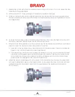
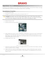
Figure 7:X-Cable Tension Adjustment
2. Using a small wrench grip the M4 Nut (shown in picture 7 above) and with a pair of pliers or cre-
sent wrench grip the X-Cable Stud at the end of the X-Cable as shown in picture above.
• Pay attention to the threads of the threaded end of the cable to rotate the M4 Nut to tighten
or loosen the X-Cable tension.
3. Remove the tools and gauge.
4. Move the X-Beam full travel to the front and back and the X-Carriage full travel left and right a
few times to ensure proper settling of the X-Cable tension.
5.
Repeat steps 2 – 5 in the “Determining if an X-Cable is Set to Required Specifications” section and
verify that the X-Cable is now adjusted to required specifications. If the X-Cable tension is adjust
-
ed properly, remove the fixture and re-install the Side Cover. If the X-Cable tension is still not ad
-
justed properly, repeat steps 1-4 in “Adjusting an X-Cable that is Tensioned Outside the Required
Specifications“ section until the X-Cable tension is adjusted correctly.
Adjusting the Tension on a Replacement X-Cable
1. If a new X-Cable had to be installed on the machine, the initial X-Cable tension adjustment should
align the X-Cable with the smaller cutout area just below the main tension cutout on the X-Cable
Tension Gauge.
2.
Follow steps 1-4 in the “Determining if an X-Cable is Set to Required Specifications” section
above to properly position the X-Cable Tension Gauge on the X-Cable.
3. Follow steps 1-3 in the “Adjusting an X-Cable that is Tensioned Outside the Required
Specifications“ section above to adjust the tension in the X-Cable until the X-Cable aligns with the
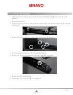
small cut out in the X-Cable Tension Gauge as shown in picture 12 below.
4. After initial adjustment of the tension in the new X-Cable the X-Cable will stretch (= X-Cable
tension will decrease) to a point where the X-Cable will fall within the required operating range as
shown in picture 6.
Table of Contents
Содержание Bravo
Страница 1: ...Technical Manual Rev 082115 ...

