82 of 271
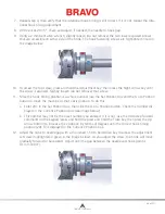
4. Position the X-Cable Tension Gauge on the X-Cable as shown in picture 5 below. Center the
Gauge between the indicated Pulley and the Upper Arm.
Figure 4: Centering the X-Carriage
5. A properly adjusted X-Cable will fall within the cutout area shown in picture 6 below. If the X ca-
ble falls within the cutout area, remove the fixture and re-install the Side Cover.
Figure 5: Positioning the X-Cable Tension Gauge
6. An improperly adjusted X-Cable will be positioned outside, either above (tension too low) or be-
low (tension too high), the cutout area as shown in pictures 7 and 8 below. In this case the ten-
sion of the X-Cable requires adjustment. Follow steps 1-5 in the section below to properly adjust
the tension of the X-Cable.
Figure 6: Inspecting X-Cable Tension
Adjusting an X-Cable that is Tensioned Outside the Required Specifications
1. Locate the M4 Nut and the X-Cable Stud at the end of the X-Cable where it mounts to the front
of the Upper Arm as shown in figure 8 below.
Table of Contents
Содержание Bravo
Страница 1: ...Technical Manual Rev 082115 ...


