133 of 271
6. Disconnect both the z-motor harness and motor and hall sensor leads (marked “CONTROL PCB Z
MOTOR” and “CONTROL PCB Z HALL/ENC”) from the main PCB at connector locations J7 and J8.
7. Use a small pair of wire cutters and cut off the cable ties that tie the z-harness to the user inter-
face harness.
8. Pull the z-harness all the way through the cable through-hole to the back of the machine and let
the harness hang off the back of the machine.
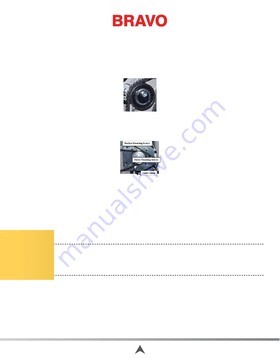
Figure 3 - Z-Belt Idler Pulley
9. Slowly loosen the z-belt idler pulley to remove the tension from the z-drive belt.
10. Cut all of the cable ties that tie the x- and z-harness leads together.
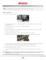
Figure 4 - Z-Motor Mounting Screws
11. Remove the cable clamp located at the bottom of the z-motor mounting bracket.
12. Remove the bracket mounting screws as shown in Figure 4 above.
13. Pull the x-cable out of the way and remove the z-motor from the machine.
14. Remove the z-motor timing pulley from the z-motor.
15. Remove the z-motor mounting bracket from the z-motor, install it on the replacement motor, and
tighten the screws to the torque specifications.
CAUTION!!
Do not drop the z-motor timing pulley or allow the star washers that are pressed
inside the bore to come loose. If the star washers fall out or come loose, the timing pulley must
be replaced. If you install a timing pulley with the star washers loose or missing, damage to the
machine will likely result.
16. Install the z-motor timing pulley onto the z-motor shaft and tighten the screw to 8 in-lbs[0.9 Nm].
This must be done with a reliable torque wrench.
17. Mount the motor assembly to the upper arm as shown in Figure 4 above and tighten the screws
to The torque specifications.
18. Use a cable tie and tie the z-motor harness to the adjacent harness leads at the z-motor mount
standoff (x-harness leads and the Control Board LED lead).
Table of Contents
Содержание Bravo
Страница 1: ...Technical Manual Rev 082115 ...


