74
GTXI User's Guide
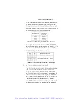
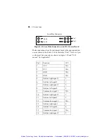
These switches are identified as described in Table 3-4.
SW1-5 to 10 A9-A4
Base address of the instrument card. These switches
must be set to the same logic position as the
instrument board base I/O Address.
SW2-9 to
SW1-4
A15-A10
Offset address value by increments of 0400h. ‘Off’
position is ‘1’ and ‘On’ position is ‘0’. If any of the
A12EN-A10EN are in the ‘Off’ position, the
increments will be different.
SW2-8
A4EN
A4 Enable. Set to “Off” when the board uses A4 for
internal decoding (up to 32 consecutive addresses).
When this switch is in the ‘On’ position, A4 is
enabled in the carrier decoding. When in the ‘Off’
position, A4 is masked out. This switch must be set
to ‘Off’ if A4 address line is not used for base
address decoding on the instrument board.
SW2-7
A5EN
A5 Enable. Set to “Off” when the board uses A5 for
internal decoding (up to 64 consecutive addresses).
When this switch is in the ‘On’ position, A5 is
enabled in the carrier decoding. When in the ‘Off’
position, A5 is masked out. This switch must be set
to ‘Off’ if A5 address line is not used for base
address decoding on the instrument board. When
702EN switch is set to ‘On’ this switch acts as the
A8EN switch of the GTXI-702 carrier.
SW2-4 to 6
A12EN-
A10EN
A12, A11, and A10 Enable. When these switches are
in the ‘On’ position, A10-A12 are enabled in the
carrier decoding. When in the ‘Off’ position, the
respective address bit is masked out. These switches
must be set to ‘Off’ if the respective address line is
used for internal decoding on the instrument board.
SW2-3 702EN
GTXI-702 Compatible Mode. When this switch is in
the ‘On’ position, base address decoding is disabled
and SW2-7 acts as the A8EN switch of the GTXI-702
carrier.
SW2-2 PnPEN
Plug and Play Mode. When this switch is in the ‘On’
position, base address range 0x274-0x27B is always
enabled regardless of the position of address
switches.
SW2-1 16BitEN
16 Bit Mode. When this switch is in the ‘On’
position, and the set address (offset AND base) is
detected, the carrier will assert the IOCS16 signal. If
any of the MemS signals are asserted, the carrier
asserts the MEMCS16 signal.
Table 3-12: GT7021 Switch Assignments
Offsets can be between 0000H and FC00H in increments of 400H,
800H, 1000H, or 2000H, depending on switch settings.
Artisan Technology Group - Quality Instrumentation ... Guaranteed | (888) 88-SOURCE | www.artisantg.com
Содержание Geotest GT7700
Страница 113: ...98 GTXI User s Guide Artisan Technology Group Quality Instrumentation Guaranteed 888 88 SOURCE www artisantg com ...
Страница 139: ...Artisan Technology Group Quality Instrumentation Guaranteed 888 88 SOURCE www artisantg com ...
Страница 145: ...Artisan Technology Group Quality Instrumentation Guaranteed 888 88 SOURCE www artisantg com ...
Страница 191: ...176 GTXI User s Guide Artisan Technology Group Quality Instrumentation Guaranteed 888 88 SOURCE www artisantg com ...
Страница 209: ...Chapter 3 Index 194 Artisan Technology Group Quality Instrumentation Guaranteed 888 88 SOURCE www artisantg com ...


