background image

Appendix D – GTXI Buffer Board   


155


IA Name Description 

Default 


Value 

MSA 

Memory Start Address for 
MEMS0 

xx00 

MEA 

Memory End Address for 
MEMS0 

xx00 

MMR 

Memory Mask Register and 
enable mode 

xx00 

DMR 

DMA Mask Register 

xx00 

IMR 

IRQ Mask Register 

xx00 

Table D-2: Internal Address Register Descriptions 

I/O Space 

The basic PC I/O space is 1kbyte - 000h-3FFh. The GTXI buffer 
divides this space into blocks. Some of these blocks can be assigned 
to the GTXI by writing to the IOM0 and IOM1 registers. The power 
up default I/O space is addresses 200-23Fh and 300-33Fh. 

I/O Mask Register 0 (IOM0) 

Internal address (IA) is 0. 


Bit # 

15-12 

11-0 

Function U 

IOE11-IOE0 

Table D-3: I/O Mask Register 0 Bit Functions 

U  

Unused 

IOE  

I/O block enable. ‘0’ - block disabled. ‘1’ - block enabled. 
See the table on the next page for bit assignments. 

The default value for bits 11-0 is 000h (all disabled). 

Artisan Technology Group - Quality Instrumentation ... Guaranteed | (888) 88-SOURCE | www.artisantg.com

Содержание Geotest GT7700

Страница 1: ...l service in house repair center WE BUY USED EQUIPMENT Sell your excess underutilized and idle used equipment We also offer credit for buy backs and trade ins www artisantg com WeBuyEquipment REMOTE INSPECTION Remotely inspect equipment before purchasing with our interactive website at www instraview com LOOKING FOR MORE INFORMATION Visit us on the web at www artisantg com for more information on ...

Страница 2: ...I TM Instrumentation Platforms GT7700 GTXI 700 User s Guide Revision 5 03 05 2003 GEOTEST MARVIN TEST SYSTEMS INC Artisan Technology Group Quality Instrumentation Guaranteed 888 88 SOURCE www artisantg com ...

Страница 3: ...ii GTXI User s Guide Artisan Technology Group Quality Instrumentation Guaranteed 888 88 SOURCE www artisantg com ...

Страница 4: ...er areas where they might be dropped or be exposed to strong electromagnetic or electrostatic fields Boards should be stored in protective anti electrostatic wrapping and away from electromagnetic fields Be sure to make a single copy of the software diskette and store the original in a safe place away from electromagnetic or electrostatic fields Warranty Geotest products are warranted against defe...

Страница 5: ...ific Standard Time Disclaimer In no event shall Geotest or any of its representatives be liable for any consequential damages whatsoever including unlimited damages for loss of business profits business interruption loss of business information or any other losses arising out of the use of or inability to use this product even if Geotest has been advised of the possibility for such damages Copyrig...

Страница 6: ... 98 NT ME 2000 and XP Microsoft Corporation All other trademarks are the property of their respective owners Patent The GTXI Instrumentation Platform including the chassis the front loading mechanism the carrier boards the extended input output addressing and the dual power supply configuration is covered by U S Patent 5 592 366 Artisan Technology Group Quality Instrumentation Guaranteed 888 88 SO...

Страница 7: ...iv GTXI User s Guide Artisan Technology Group Quality Instrumentation Guaranteed 888 88 SOURCE www artisantg com ...

Страница 8: ...Platform 4 GTPC 7586 Controller Module with GTXI 700 only 4 Carrier Boards 4 GTXI 704 Extended Carrier Board 5 GTXI 701 PC Bus Expansion Kit 5 GTXI 7710 Expansion Chassis System 5 Comparing the GTXI 700 and GT7700 Platforms 6 GTXI 700 as a Stand Alone Computer Platform 9 GTXI 700 as a Bus Extender 10 GTXI 7710 Expansion Chassis System 12 Features 12 System Block Diagram 13 Artisan Technology Group...

Страница 9: ...ode 22 Local Bus 22 Interfacing 25 External Instrumentation 25 Cooling 25 Chapter 2 Installing and Operating 27 Unpacking and inspecting the GTXI 27 Setting up the GTXI 27 Selecting Line Voltage 28 Installing the GT7700 30 Installing the GTXI 700 for standalone Mode 33 Installing the GTXI 700 for Bus Extender Mode 39 Installing GT7710 Expansion Chassis System 43 Powering up the system 44 Setting U...

Страница 10: ...Base Address 55 Setting ISA Carrier Board I O Addressing 56 Setting the GTXI 702 Carrier Board I O Address 59 Setting the DIP Switches 60 Setting the GT7020 Carrier Board I O Address 64 Setting the DIP Switches 66 Setting the GT7021 Carrier Board I O Addressing 73 Setting the DIP Switches 75 Configuring Plug and Play Boards 82 Setting ISA Carrier Board DMA Select 82 Setting ISA Carrier Board Memor...

Страница 11: ...5 Installing PC Boards on the GTPC GT7586 Controller Module 96 Installing PC Boards on the GT7700 System Controller Module 97 Chapter 4 Assigning Resources 99 ISA Bus Hardware Buffering 99 The GTXI Config Utility 100 When to Use GTXI Config ISA boards only 101 Installing GTXI Config 101 Starting GTXI Config 103 To start GTXI Config from the command line 103 To start GTXI Config from the program ic...

Страница 12: ...nnels View 116 To change IRQ channel assignments 117 DMA Channels View 118 To change DMA channel assignments 118 Applying Configuration Changes 120 Applying Configuration Changes on Startup 120 The GTXI INI File 122 Appendix A GTXI Specifications 126 AC Input Power 126 Power Supplies 126 GT 7700 Chassis 126 GTXI 700 Chassis 127 Cooling 128 Slots 128 Physical Dimensions 128 System Controller Module...

Страница 13: ...XI 700 141 Front and Back Views of the GT7700 144 Replacing a GTPC Keyboard or Mouse Cable 146 Replacing a Power Switch 148 Replacing a damaged wire on mouse cable 149 Replacing a damaged wire on Keyboard cable 151 Replacing a Light Bulb on a Power Switch 152 Appendix D GTXI Buffer Board 153 The GTXI Buffer Board Registers 153 Internal Address Register IAR 154 I O Space 155 I O Mask Register 0 IOM...

Страница 14: ...ion 166 Setup of the GTXI 750 Interface 167 Unpacking and inspecting the Interface 167 Installation of the GTXI Interfaces 168 Remove the Original GTXI Door 168 Add the GTXI Interface Door 168 Connect the Cables 168 Configure and Install the Interface 170 Prototype Areas 170 CANNON GTXI 750 Pin Out Listing 171 Introduction 171 Cannon Panel Pin Out Connections 173 Connector CP1 Front View Component...

Страница 15: ...79 Unpacking and inspecting the Interface 179 Installation of the GTXI Interfaces 180 Remove the Original GTXI Door 180 Add the GTXI Interface Door 180 Connect the Cables 180 Configure and Install the Interface 182 Virginia GTXI 760 Pin Out Listing 184 Index 189 Artisan Technology Group Quality Instrumentation Guaranteed 888 88 SOURCE www artisantg com ...

Страница 16: ...sign of the GTXI allows integration of PC boards from any vendor using a VXI like platform Both GTXI models offer the following features Front loading mechanism Boards are inserted from the front without the need to open a cover as with a regular PC Board connectors face the front side of the platform enabling easy access to board connectors and cables In this manual when referring to features of ...

Страница 17: ...o the system than a regular PC can hold GTXI 700 systems can be extended by connecting up to four GTXI units to a host PC in a star topology accommodating up to 52 ISA front loading plug in boards in one system GT7700 systems can be extended by connecting one GT7700 and up to two GTXI 700 units in a star topology accommodating up to 34 ISA and 4 PCI front loading plug in boards in one system GT770...

Страница 18: ...e used to expand the system to accommodate non PC instruments When bundled with ATEasy Geotest s software development environment the GTXI provides a complete system for creating test and measurement applications Artisan Technology Group Quality Instrumentation Guaranteed 888 88 SOURCE www artisantg com ...

Страница 19: ...mpatible 16 bit including an all in one controller board Pentium CPU floppy and hard disk drives SVGA interface two RS 232 ports and a parallel port The module also provides two spare ISA slots for special I O interfaces such as Ethernet LAN GPIB MXI VXI or any other ISA based board The module comes with a buffer board providing bus isolation when passing ISA signals to boards installed on the pla...

Страница 20: ...ter or from a GT7700 instead of from an embedded GTPC 7586 controller module The expansion kit can also be used to connect up to four GTXI 700 platforms to a host PC in a star topology GTXI 7710 Expansion Chassis System The GT7710 is an expansion chassis that provides additional expansion card slots to a host PC This expansion chassis supports most commercial PC bus standards such as PCI and ISA C...

Страница 21: ... talk Two rear mounted fans provide efficient cooling for chassis instrumentation Two fans cool the power supplies Up to 13 top mounted fans can be added to meet extra localized cooling needs Two separate power supplies add flexibility and reliability One supply powers the controller while the other powers instrumentation One supply powers the controller and PCI bus the other powers ISA bus instru...

Страница 22: ...r 34 ISA and 6 PCI boards using one GT7700 and two GTXI 700 chassis supports total of 40 boards Up to 20 ISA and 15 PCI or 22 ISA and 13 PCI using one GT7700 and two GT7710 Expansion Chassis Supports up to 35 boards A built in interface panel accommodates interface adapters passing or receiving signals from the Unit Under Test UUT Standard and optional interface panels are available External instr...

Страница 23: ...VDC for PCI slots System Controller GTPC available Contains SBC Single Board Computer buffer board and 2 spare ISA slots Contains SBC 1 ISA 1 PCI and 1 shared ISA PCI slot in the embedded controller module External Controller Accepts external PC as a controller The GT7710 accepts an external PC as a controller Table 1 1 Comparison of Features of the GTXI 700 and GT7700 Artisan Technology Group Qua...

Страница 24: ...s Figure 1 1 and Figure 1 2 show the GTXI 700 platform with a GTPC 7586 controller module The controller module uses four slots on the platform leaving 10 GTXI slots available for boards The controller module comes with a floppy disk drive a hard disk drive and four ISA slots One ISA slot is used by the single board computer SBC and another by the buffer board leaving two standard ISA slots availa...

Страница 25: ...on the host computer must contain a GTXI 701 PCT Bus Expander Board sometimes called a transmitter board The transmitter board is connected by a six foot shielded cable to a GTXI 701 PCR Bus Receiver Board on the GTXI 700 it sends and receives the ISA bus signals between the host PC and the instrument platform Up to 13 ISA boards can be installed in the GTXI 700 in this mode GTPC Instrument Boards...

Страница 26: ...e 1 3 GTXI 700 and PC Connected fully expandable configuration The resulting system enables any choice of computer to control boards that reside in the GTXI 700 as shown in Figure 1 3 As many as four GTXI 700 units can be connected in this way Artisan Technology Group Quality Instrumentation Guaranteed 888 88 SOURCE www artisantg com ...

Страница 27: ...n cables The cables connect to PCI and ISA backplane controller cards installed in the expansion chassis The PCI backplane controller card must be loaded into the left most PCI slot of the GT7710 The ISA backplane controller card is loaded into the right most ISA slot of the GT7710 Features Front loading of all instrument cards Supports ISA instrument Cards ISA Cards may be powered down and remove...

Страница 28: ...an be used by either a PCI card or a ISA card not both Host PC GT7710 Expansion Chassis ISA Host Card Plugs into any ISA slot PCI Host Card Plugs into any PCI busmaster capable slot PCI PXI CPCI Bus Controller Card plugs into left most slot Supports up to 6 PCI cards ISA Bus Controller Card plugs into right most slot Supports up to 7 ISA cards PCI Cable Local Bus ISA Cable Artisan Technology Group...

Страница 29: ...ng a method similar to that found on VXI VME systems Front loading is a major improvement over the top loading method used on desktop and standard industrial computers since the computer does not need to be opened or taken apart in order to remove or insert boards The board connectors face the front making it easier to connect cables The carrier board s PCB power planes buffer and shield the PC pl...

Страница 30: ...a GTXI 700 depends on whether it is used as a stand alone PC or as a bus extender Since the GTPC controller module occupies four slots the GTXI 700 has room for ten instruments or PC boards in stand alone mode In bus extender mode the far right slot must be reserved for the GTXI 701 PCR Receiver Board leaving 13 slots Artisan Technology Group Quality Instrumentation Guaranteed 888 88 SOURCE www ar...

Страница 31: ...ots The GT7700 has 11 slots for GTXI designed carrier boards Eight slots maximum can be used for ISA boards while four slots maximum can be used for PCI boards PCI and 8 or 16 bit ISA bus PC boards from any vendor are loaded onto GTXI carrier boards and then placed in available slots in the chassis Artisan Technology Group Quality Instrumentation Guaranteed 888 88 SOURCE www artisantg com ...

Страница 32: ...ystem Controller PCI bus slots ISA bus slots Figure 1 8 GT7700A Instrumentation Platform Figure 1 9 GT7700B Instrumentation Platform Artisan Technology Group Quality Instrumentation Guaranteed 888 88 SOURCE www artisantg com ...

Страница 33: ... PCI cards Slots 4 5 Shared PCI ISA one actual slot Slot 1 Slot 11 Slot 12 System Controller Module Figure 1 10 GT7700 Slot Numbers ISA Bus Isolation The GTXI s instrumentation platform ISA bus is completely buffered providing isolation between the boards and between the controller and the boards When the GTXI 700 is used as a stand alone PC with a GTPC 7586 controller module see Figure 1 11 a buf...

Страница 34: ... from the instrumentation platform by the buffer board and the carrier board This isolation not only safeguards the controller from any hazardous condition it also prevents any single instrument from hanging up the bus and disabling the entire system Artisan Technology Group Quality Instrumentation Guaranteed 888 88 SOURCE www artisantg com ...

Страница 35: ...d Addressing The isolation of the CPU from instrumentation extends to the PC board I O address using offset I O address re mapping This makes more I O addresses available increasing the number of boards GTXI based system can use well beyond that of a conventional PC The GTXI s extended I O addressing is illustrated above Artisan Technology Group Quality Instrumentation Guaranteed 888 88 SOURCE www...

Страница 36: ...oving any additional mechanical parts or rebooting to reload software Power Supplies for the GTXI 700 standalone Mode When the GTXI 700 operates as a stand alone PC with a GTPC 7586 controller one power supply is used by the plug in controller module while the second power supply drives the instrument board section of the platform The main power switch turns on the computer related circuitry only ...

Страница 37: ...he host PC Both power supplies must be on to operate any board in the chassis Note For information on reconfiguring the power supplies please contact Geotest Local Bus Some applications require interconnections between the instruments The GTXI 700 offers an internal 22 line local bus for intercard signal transfers See Figure 1 13 The GT7700 and GT7710 both offers an internal 22 line local bus for ...

Страница 38: ... of the lines may be configured into several sub buses serving selected boards only Adjacent ISA instrument boards on carrier boards can be connected to each other with the sub buses All ISA and PCI instruments can be connected with the common local bus The local bus connector on the carrier board is used to interface to the local bus and the sub buses on the GTXI 700 Artisan Technology Group Qual...

Страница 39: ... lines ISA Carrier Board ISA Board ISA Board PCI Carrier Board PCI Board PCI Boards ISA Boards Figure 1 14 GT7700GT7710 Local Bus Architecture On the GT7700 and GT7710 the local bus architecture contains no sub buses for PCI slots See Chapter 3 Using the Local Bus for more information Artisan Technology Group Quality Instrumentation Guaranteed 888 88 SOURCE www artisantg com ...

Страница 40: ...See Appendix D GTXI 750 Cannon ITT Interface or Appendix E GTXI 760 Virginia Panel Interface for further details on options External Instrumentation The GTXI System can be expanded to control external instruments Two RS 232C serial ports are available one used for a mouse In addition an optional IEEE 488 GPIB or VXI MXI interface board can be added to control other non PC instruments Cooling The G...

Страница 41: ...26 GTXI User s Guide Artisan Technology Group Quality Instrumentation Guaranteed 888 88 SOURCE www artisantg com ...

Страница 42: ...items defects or damage are noticed notify Geotest immediately Setting up the GTXI The GTXI unit is shipped as a stand alone system or as a bus extender system If instrumentation boards are ordered they will be installed on GTXI carrier boards and put inside the platform For installation details refer to the appropriate section Installing the GT7700 Installing the GT7710 Installing the GTXI 700 fo...

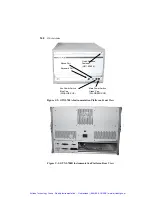
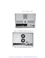
Страница 43: ...uired Use the line voltage switch on the rear panel of the GTXI platform to switch from 110V to 220V as needed Figure 2 1 and Figure 2 2 show the location of the line voltage switch on the GTXI 700 Figure 2 2 and Figure 2 4 show the location of the line voltage switch on the GT7700 Line Voltage Switch AC Line Receptacle VGA Port COM2 Port Parallel Port Fans Figure 2 1 GTXI 700A Rear View Artisan T...

Страница 44: ... Line Receptacle Fans VGA COM Parallel Line Voltage Switch 110 220 GPIB LAN Figure 2 3 GT7700A Rear View GPIB VGA Parallel Serial USB Ethernet AC Line Receptacle Line Voltage Switch 110 220 Artisan Technology Group Quality Instrumentation Guaranteed 888 88 SOURCE www artisantg com ...

Страница 45: ...lar work surface or Mounting it in a standard 19 inch 24 inch deep equipment rack using the optional GT7700R Rack Mount Kit 2 Set the line voltage to 110V or 220V as needed by the line voltage switch on the rear of the GT7700 See Figure 2 2 and Figure 2 4 VGA GBIP Serial Parallel USB Ethernet Line Voltage Switch 110 220 AC Line Receptacle Artisan Technology Group Quality Instrumentation Guaranteed...

Страница 46: ... Connect the keyboard and mouse cables to the lower front panel of the GT7700 See Figure 2 2 Figure 2 5 GT7700B Instrumentation Platform Front Panel Artisan Technology Group Quality Instrumentation Guaranteed 888 88 SOURCE www artisantg com ...

Страница 47: ...wer cord to the back of the GT7700 and plug it in receptacle See Figure 2 3 and Figure 2 4 for the location of the AC Line Receptacle 7 Turn on the power to the GT7700 platform by pressing both the Main and the Auxiliary switches and wait for the boot sequence to complete Note Some PC based instruments require that their drivers be loaded by the CONFIG SYS file This is the reason the main power su...

Страница 48: ...similar to those used on a GTXI 701 PCT bus Expander Board as described in more detail in the section Installing the GTXI 700 for Bus Extender Mode on page 39 The following steps are required to set up the GTXI 700 in stand alone mode 1 Mount the GTXI 700 unit with its GTPC controller module by either placing it on a regular work surface or Mounting it in a standard 19 inch 24 inch deep equipment ...

Страница 49: ...x Power Switch Mouse Port Keyboard Port Quick Release Fastener Green Main Power Switch Figure 2 7 GTXI 700A Instrumentation Platform Front View Figure 2 8 GTXI 700B Instrumentation Platform Front View Main Switch Aux Switch Serial Mouse Keyboard USB Artisan Technology Group Quality Instrumentation Guaranteed 888 88 SOURCE www artisantg com ...

Страница 50: ...perating 35 VGA PS 2 Mouse COM1 COM2 LPT1 Keyboard Two empty ISA slots Floppy Drive Figure 2 9 Connections on the front of the GTPC 7586 Artisan Technology Group Quality Instrumentation Guaranteed 888 88 SOURCE www artisantg com ...

Страница 51: ...36 GTXI User s Guide Instrument Boards GTPC Cable Tray Figure 2 10 GTXI 700A showing the cable tray area Artisan Technology Group Quality Instrumentation Guaranteed 888 88 SOURCE www artisantg com ...

Страница 52: ...the port on the rear of the GTXI as shown in Figure 2 1 and Figure 2 2 6 If a printer is to be used connect the printer cable to the port on the rear of the GTXI as shown in Figure 2 1and Figure 2 2 GTPC Cable Tray Instrument Boards Artisan Technology Group Quality Instrumentation Guaranteed 888 88 SOURCE www artisantg com ...

Страница 53: ...he Auxiliary switches at the same time Wait for the boot sequence to complete Note Some PC based instruments require that their drivers be loaded by the CONFIG SYS file This is the reason the GTXI 700 instruments are turned on at the same time with the GTPC controller module 9 Run the GTXI utility program GTXICFG EXE This utility is used to assign resources to and from the GTPC and the GTXI 700 Ve...

Страница 54: ...1PCT board are labeled Disable All MEM IRQ DMA SEL1 SEL0 ON 0 The last four switches DMA IRQ MEM and ALL are set by default to OFF set to the down position This position enables these signals through the transmitter board and makes them available for the boards installed in the platform In the ON position these switches can also be used to disable the signals from passing through the transmitter b...

Страница 55: ... 14 shows an example of a single DIP switch setting On Off The switch is pushed up The switch is pushed down Figure 2 14 ON and OFF positions for a DIP switch The DIP switch settings and base addresses for the four possible boards are listed in the following table Board Base Address SEL1 SEL0 1st 178 17B On On 2nd 17C 17F Off On 3rd 57C 57F On Off 4th 578 57B Off Off Table 2 1 DIP switch settings ...

Страница 56: ...used only when connecting multiple GTXI platforms in a daisy chain arrangement contact Geotest technical support for further information J4 is for the local bus J3 is for the ISA bus 7 Using the 6 foot shielded cable provided with the Bus Expansion Kit connect the GTXI 701 PCT board in the host PC to the GTXI 701 PCR board that is installed in slot 13 of the GTXI system platform If the GTXI unit w...

Страница 57: ...the GTXI configuration diskette This will edit the host computer s AUTOEXEC BAT file and install a special GTXI utility program called GTXICFG EXE This utility is used to assign resources to and from the host PC and the GTXI platform Refer to Chapters 3 and 4 for further instructions 13 To change and apply that configuration run the GTXICFG utility make the desired changes and save Then apply the ...

Страница 58: ...tender Mode above in this chapter 5 Install the GTXI 701 PCT Bus Expander Board into a 16 bit ISA slot on the host PC 6 Install the SBS 200 2 PCI Host Card into a bus master capable PCI slot on the host PC The slot can be either 3 3V or 5 0V and either 32 or 64 bit PCI Refer to Chapter 3of the SBS Model 200 2 PCI Host Card Hardware Manual 7 Install the GTXI 701 PCR Bus Receiver Board into the righ...

Страница 59: ...e GT7710 Expansion Chassis must be reconfigured every time power is cycled Rebooting or resetting the host PC reconfigures it Setting Up with Multiple GTXI Platforms If you need to use more instrument boards than will fit into a single GTXI platform you can expand the GTXI system by connecting additional GTXI platforms to accommodate additional instrument boards With a GT7700 When the GTXI 700 is ...

Страница 60: ... slots are needed contact Geotest for additional configurations GT7700 Slave GTXI 700 PCT Boards PCR Boards Cabling Slave GTXI 700 Figure 2 16 GT7700 connected to two GTXI 700s With a stand alone GTXI 700 When the GTXI 700 is used as a stand alone computer platform the GTPC 7586 module contains four board slots A GTXI 701 PCT transmitter board can be placed in any open slot in the GTPC module and ...

Страница 61: ...or additional configurations Using offset addresses for the GTXI up to 64 possible slots can be used With a Host Computer When the GTXI is used as a bus extender system connected to a host PC a GTXI 701 PCT transmitter board must be placed in one ISA slot on the host PC On the GTXI platform place a GTXI 701 PCR receiver board in the far right slot 13 in each of the GTXI platform Using cabling conn...

Страница 62: ...n receiver boards for a total of four GTXI 700 platforms See Figure 2 18 for a configuration using two GTXI 700 platforms Thus it is possible to have up to 52 ISA instrument slots connected on one host computer with four slave GTXI 700 platforms thirteen slots each If more than 52 slots are needed contact Geotest for additional configurations Using offset addresses for the GTXI up to 64 possible s...

Страница 63: ...ower on Sequence Aux switch Main switch Figure 2 19 GTXI Power Switches Figure 2 20 GTXI 700B Power Switches Main Switch Aux Switch Artisan Technology Group Quality Instrumentation Guaranteed 888 88 SOURCE www artisantg com ...

Страница 64: ...he Main and Auxiliary switches at the same time and waiting for the boot sequence to complete Note Some PC based instruments require their drivers be loaded by the CONFIG SYS file This is the reason the controller is turned on at the same time as the instrumentation Power on Sequence for GTXI 700 in Bus Extender Mode 1 Turn on the GTXI 700 platform Main and Auxiliary switches 2 Turn on the host co...

Страница 65: ...power is off If attempts are made to try to access boards on the platform while the auxiliary power is off the results are unpredictable and the computer may have to be rebooted PnP and some boards may have to be reinitialized by the user or by rebooting the computer after restoring power All GTXI chassis in a system must be powered for normal operation Artisan Technology Group Quality Instrumenta...

Страница 66: ...n this chapter does not apply to them The following steps are required to install PC instrument boards in the GTXI 1 For ISA boards plan the input output addresses and resources that will be used 2 Install the instrument boards on the carrier boards 3 Optional steps see Installing PC Boards on the GTPC GT7586 Controller Module on page 96 and Installing PC Boards on the GT7700 System Controller Mod...

Страница 67: ...ne in advance whether any additional resources Memory DMA and IRQ will be used and make sure there are no resource conflicts Installing Instrument Boards on the Carrier Boards The following steps are required to install PC boards on a carrier board 1 Turn the power off to the carrier boards platform by pressing the appropriate power switch on the front the GTXI platform 2 Open the front door of th...

Страница 68: ...r and top board guides to make room for the PC board c Place the PC instrument board in the GTXI carrier board and seat it gently in the ISA or PCI bus slot on the carrier board see Figure 3 2 Make sure that no bolts or other parts of the instrument board can make contact with the carrier board when seated If they are they may need to be replaced with shorter screws plastic screws or other parts A...

Страница 69: ...C bracket on the front of the PC instrument board to the carrier board e Position the rear and top mounting board guides so that they hold the PC board firmly in place on the carrier board f Press the rear and top board guides close and tighten the screws on the backside of the board guides Artisan Technology Group Quality Instrumentation Guaranteed 888 88 SOURCE www artisantg com ...

Страница 70: ... 3F8 3FF COM1 278 27F LPT2 57C 57F PCT 3 2E0 2EF GPIB COM4 578 57B PCT 4 Table 3 1 Input Output Base Addresses In general when allocating I O addresses and any other system resources such as memory addresses DMA channels and IRQ channels to a given instrument board make sure these resources are not already allocated and used by the PC or another PC board Conflicts in resource allocation may result...

Страница 71: ...te extra leading zero for alignment Offset Address 0x1000 New Base Address 0x1300 Table 3 2 Using Offset Address Using this technique up to 64 PC boards can be installed with the same base address setting However some PC boards use some of the A10 A15 address lines for internal decoding thus reducing the number of boards that can use the same base address For example a board with base address rang...

Страница 72: ...set address is unique for each of the carrier boards on the GTXI platform There are five models of carrier boards for the GTXI system The model GT7730 for CPCI and PXI boards This model is plug and play and therefore is configured automatically by the operating system and requires no DIP switches The model GT7720 for PCI boards This model is plug and play and therefore is configured automatically ...

Страница 73: ...DIP switch SW1 Top Board Guide DMA Select SW1 DIP Switches ISA Bus Receptacle Memory Select Local Bus Connector Local Bus Jumpers Rear Board Guide J2 J1 J3 J4 J5 SW2 DIP Switches GT702x only Figure 3 3 GT702x GTXI 702 Carrier Board Artisan Technology Group Quality Instrumentation Guaranteed 888 88 SOURCE www artisantg com ...

Страница 74: ...ion is 1 and On position is 0 SW1 5 A11 Offset value by increments of 0800h A11EN must be in Off position to enable this offsetting SW1 6 7 A8EN A11EN When these switches are in Off position A8 and A11are enabled When in On position the carrier board s offset switch settings are compatible with older versions of the carrier SW1 8 A8 This switch allows two carrier boards to be used with the same of...

Страница 75: ...Off Off Off Off Table 3 6 GTXI 702 Address Switch Settings Example Setting the DIP Switches The procedure for determining the DIP switch settings is explained below As a general rule note that no two carrier boards can have the same combination of DIP switch settings 1 Set the offset address in increments of 1000H a Start by converting the hexadecimal address into binary see Table 3 9 Hexadecimal ...

Страница 76: ...If two carrier boards have the same offset addresses A15 through A11EN then use the A8 A8EN switches to differentiate them a For example one board might have A15 A14 A13 A12 A11 A11 EN A8 EN A8 0 0 0 1 1 1 1 0 b while the other board would have A15 A14 A13 A12 A11 A11 EN A8 EN A8 0 0 0 1 1 1 1 1 The table below shows the carrier board switch settings for offsets ranging from 0H to F800H The X 2 3 ...

Страница 77: ...ff On On X 2 3 X 2 3 4800 On Off On On Off Off 5000 On Off On Off X 2 3 X 2 3 5800 On Off On Off Off Off 6000 On Off Off On X 2 3 X 2 3 6800 On Off Off On Off Off 7000 On Off Off Off X 2 3 X 2 3 7800 On Off Off Off Off Off 8000 Off On On On X 2 3 X 2 3 8800 Off On On On Off Off 9000 Off On On Off X 2 3 X 2 3 9800 Off On On Off Off Off A000 Off On Off On X 2 3 X 2 3 A800 Off On Off On Off Off Artis...

Страница 78: ...ffset address If A8 is used two boards can be in the same offset They must not reside in the same address group 200h 2FFh and 300h 3FFh 2 For offset address n000H A11EN and A11 should be Off if address n800H is to be used 3 If A11 is not enabled set to OFF then a carrier using address n000H is also occupying address n800H For convenience it is recommended that the ISA carrier slot number multiplie...

Страница 79: ...g On On On On Off Off On On On On On On On ADDRESS MASK OFFSET ADDRESS BASE ADDRESS ENABLE DISABLE SW2 SW1 0 1 Off Off Off Figure 3 4 GT7020 address switches for 0x2300 offset A typical setting for the DIP switches SW2 and SW1 for a GT7020 is given in the following figure These switches are identified as described in Table 3 8 Artisan Technology Group Quality Instrumentation Guaranteed 888 88 SOUR...

Страница 80: ...led in the carrier decoding When in the Off position A4 is masked out This switch must be set to Off if A4 address line is not used for base address decoding on the instrument board SW2 1 to 3 A12EN A10EN A12 A11 and A10 Enable When these switches are in the On position A10 A12 are enabled in the carrier decoding When in the Off position the respective address bit is masked out These switches must...

Страница 81: ...1 0001 2 0010 3 0011 4 0100 5 0101 6 0110 7 0111 8 1000 9 1001 A 1010 B 1011 C 1100 D 1101 E 1110 F 1111 Table 3 9 Hexadecimal to binary conversion table b Use the binary value to set the switches 0 on 1 off starting at A0 on the right and working toward A15 on the left using as many switches as necessary For example 2A0H is 10 1010 0000 A3 through A0 are ignored here as indicated by the shading T...

Страница 82: ... address mask optional An A4EN address mask is used to allow ignoring the A4 switch so a larger address range can be accessed With A4EN on every setting of one offset and base address uses sixteen addresses A0 through A3 For example if a board uses a range of addresses for I O say the 20 addresses from 300H to 313H then the addresses in the range of 300H through 30FH have A4 0 up to sixteen addres...

Страница 83: ...701H A10EN must be set to OFF The default settings for the address masks are A4EN ON Board uses 16 consecutive addresses A10EN OFF A11EN OFF Offset address increments of 1000H A12EN ON Table 3 11 A4EN through A12EN Default Settings These steps are given in greater detail in the sections that follow along with three examples Example 1 Short base address range and zero offset This example uses a bas...

Страница 84: ...set to zero so set A10 A15 to zero on 3 Set the address mask Since there is no change in A4 and A10 A12 the default address mask does not need changing even though A10 A12 can be set to zero Thus the final SW2 and SW1 settings are On On On On Off Off On On On On On On On ADDRESS MASK OFFSET ADDRESS BASE ADDRESS ENABLE DISABLE SW2 SW1 0 1 Off Off On Figure 3 5 Example 1 address switches Artisan Tec...

Страница 85: ...emember that A0 A3 are ignored A15 A14 A13 A12 A11 A10 A9 A8 A7 A6 A5 A4 0 0 0 0 0 1 1 1 0 0 0 1 The internal addresses of B10H through B13H in binary become 1011 0001 0000 through 1011 0001 0011 This translates in settings of A15 A14 A13 A12 A11 A10 A9 A8 A7 A6 A5 A4 0 0 0 0 1 0 1 1 0 0 0 1 The internal addresses of F10H through F13H in binary become 1111 0001 0000 through 1111 0001 0011 This tra...

Страница 86: ...A12 A11 A10 A9 A8 A7 A6 A5 A4 1 1 0 0 0 0 0 0 0 0 0 0 3 Set the address mask Since A12 A11 and A10 are used in internal decoding all three must have their address mask set to OFF Thus the final SW1 and SW2 settings are On On Off Off On On ADDRESS MASK OFFSET ADDRESS BASE ADDRESS ENABLE DISABLE SW2 SW1 0 1 Off Off Off Off On Off Off Figure 3 6 Example 2 address switches Artisan Technology Group Qua...

Страница 87: ...tes in settings of remember that A0 A3 are ignored A9 A8 A7 A6 A5 A4 1 0 0 0 1 0 through A9 A8 A7 A6 A5 A4 1 0 0 0 1 1 2 Set the offset address The offset address of A800H in binary becomes 1010 1000 0000 0000 which means settings of A15 A14 A13 A12 A11 A10 A9 A8 A7 A6 A5 A4 1 0 1 0 1 0 0 0 0 0 0 0 3 Set the address mask Since A4 is used in the internal decoding we will have to set A4EN OFF These ...

Страница 88: ...ressing The GT7021 has additional addressing features like GTXI 702 compatible mode Plug and Play and 16 bit addressing mode A typical setting for the DIP switches SW2 and SW1 for a GT7021 is given in the following figure Figure 3 8 GT7021 address switches for 0x2300 address On ADDRESS MASK OFFSET ADDRESS BASE ADDRESS ENABLE DISABLE SW2 SW1 0 1 Off On On On Off On On On Off On A4 A5 A6 A7 A8 A9 A1...

Страница 89: ...ddress decoding on the instrument board When 702EN switch is set to On this switch acts as the A8EN switch of the GTXI 702 carrier SW2 4 to 6 A12EN A10EN A12 A11 and A10 Enable When these switches are in the On position A10 A12 are enabled in the carrier decoding When in the Off position the respective address bit is masked out These switches must be set to Off if the respective address line is us...

Страница 90: ...art by converting the hexadecimal address into binary Hexadecimal Binary 1 0001 2 0010 3 0011 4 0100 5 0101 6 0110 7 0111 8 1000 9 1001 A 1010 B 1011 C 1100 D 1101 E 1110 F 1111 Table 3 13 Hexadecimal to binary conversion table b Use the binary value to set the switches 0 on 1 off starting at A0 on the right and working toward A15 on the left using as many switches as necessary Artisan Technology ...

Страница 91: ...s do not accept addresses greater than 3FFH If this is the case an offset address of 0000H should be used 3 Set the address mask optional An A4EN address mask is used to allow ignoring the A4 switch so that a larger address range can be accessed With A4EN on every setting of one offset and base address uses sixteen addresses A0 through A3 For example if a board uses a range of addresses for I O sa...

Страница 92: ...he addresses masks are A4EN ON Board uses no more then A5EN ON 16 consecutive addresses A10EN OFF A11EN OFF Offset address increments of 1000H A12EN ON Table 3 15 A4EN through A12EN Default Settings 4 Set the special addressing modes optional The 702EN switch is used to disable the base address decoding This combined with the PnPEN switch is useful when configuring plug and play PnP ISA boards Whe...

Страница 93: ...nd Play address range 16BitEN OFF Carrier does not assert CS16 signals These steps are given in greater detail in the sections that follow along with three examples Example 1 Short base address range and zero offset This example uses a base address range of 300H 307H and offset address of zero 1 Set the base address The base address of 300H in binary becomes 11 0000 0000 This translates in setting...

Страница 94: ...13 F10 F13H and 1310 1313H and an offset of C000H 1 Set the base address The base addresses of 310H through 313H in binary become 11 0001 0000 through 11 0001 0011 This translates in settings of remember that A0 A3 are ignored A15 A14 A13 A12 A11 A10 A9 A8 A7 A6 A5 A4 0 0 0 0 0 0 1 1 0 0 0 1 The internal addresses of 710H through 713H in binary become 111 0001 0000 through 0111 0001 0011 This tran...

Страница 95: ...ome 1 0011 0001 0000 through 1 0011 0001 0011 This translates in settings of A15 A14 A13 A12 A11 A10 A9 A8 A7 A6 A5 A4 0 0 0 1 0 0 1 1 0 0 0 1 Thus A12 A11 and A10 in the offset address area are used for internal board address decoding 2 Set the offset address The offset address of C000H in binary becomes 1100 0000 0000 0000 which means settings of A15 A14 A13 A12 A11 A10 A9 A8 A7 A6 A5 A4 1 1 0 0...

Страница 96: ... 0 1 0 through A9 A8 A7 A6 A5 A4 1 0 0 0 1 1 2 Set the offset address The offset address of A800H in binary becomes 1010 1000 0000 0000 which means settings of A15 A14 A13 A12 A11 A10 A9 A8 A7 A6 A5 A4 1 0 1 0 1 0 0 0 0 0 0 0 3 Set the address mask Since A4 and A5 are used in the internal decoding we will have to set A4EN OFF and A5EN OFF ADDRESS MASK OFFSET ADDRESS BASE ADDRESS ENABLE DISABLE SW2...

Страница 97: ... I O address assigned MemS jumpers according to memory address assigned if any and DACK jumper according to DMA channel assigned if any Setting ISA Carrier Board DMA Select For some ISA carrier boards DMA resources need to be allocated prior to operating the GTXI Check the manual for the instrument board to see if it uses DMA channels If it does 1 Determine the DMA channels without conflicts 2 Put...

Страница 98: ...ing ISA Carrier Board Memory Map Selection If the instrument board being used in the GTXI is memory mapped i e it uses controller memory address space then a memory select jumper on the ISA carrier board must be set The memory select jumpers are located in a bank on the top of the carrier board as shown in Figure 3 1and Figure 3 2 They are labeled MEMS0 through MEMS5 with the MEMS5 jumper located ...

Страница 99: ...propriate MEM addresses See Chapter 4 Assigning Resources for further details 2 User defined memory a Determine the necessary resources to the nearest 64k address range b Put the appropriate jumper on the MEMS0 MEMS1 is reserved for future variations c Make sure that MEM signals are enabled on the DIP switch on the buffer board if using the GTXI for stand alone mode or the GTXI 701 PCT Transmitter...

Страница 100: ...be anywhere in the 000000H FFFFFFH address range The block size is user defined in increments of 64K and MUST NOT overlap memory space used by the controller Using a Memory Manager Utility If the computer uses a memory management utility such as EMM386 EXE the utility must be prevented from using the area of memory reserved for the PC instrument board When Windows starts it looks for any and all m...

Страница 101: ...om each board to its local bus Local Bus Connector Local Bus Jumpers J2 J1 J3 J4 J5 Figure 3 11 ISA Carrier Board Figure 3 11shows an ISA carrier board The pins at J4 on the rear of the carrier board connect to the local bus while pins at J3 connect to the ISA Bus The local bus consists of 48 pins in three rows of 16 pins each The pins in J4 allow a carrier board to be connected to other carrier b...

Страница 102: ...n carrier boards See Figure 3 13 and Table 3 14 for a description of the pins on the carrier s local bus connector The local bus connector has 40 pins 10 of which connect to the common bus These 10 lines are common to all ISA carrier boards but only six are common to PCI carrier boards Twelve of these connect ISA boards to the carrier board to the right on the GTXI platform Twelve others connect I...

Страница 103: ...3 10 and N A means Not Applicable Pin Function JP 1 VCC N A 2 VCC N A 3 GND N A 4 GND N A 5 Sub bus right signal 1 1 6 Sub bus left signal 1 1 7 Sub bus right signal 2 2 8 Sub bus left signal 2 2 9 Common bus signal 1 N A 10 Sub bus right signal 3 3 11 Sub bus left signal 3 3 12 Common bus signal 2 N A 13 Sub bus right signal 4 14 Sub bus left signal 4 4 15 Common bus signal 3 N A 16 Sub bus right...

Страница 104: ...bus left signal 8 8 27 Common bus signal 7 N A 28 Sub bus right signal 9 9 29 Sub bus left signal 9 9 30 Common bus signal 8 N A 31 Sub bus right signal 10 10 32 Sub bus left signal 10 10 33 Common bus signal 9 N A 34 Sub bus right signal 11 11 35 Sub bus left signal 11 11 36 Common bus signal 10 N A 37 Sub bus right signal 12 12 38 Sub bus left signal 12 12 39 GND N A 40 GND N A Table 3 17 Local ...

Страница 105: ...o connected to the common bus for that signal Connecting Adjacent Boards via a Sub bus Most users prefer to place the two instrument boards that need to be connected adjacent to each other on the GTXI platform and use a sub bus The sub bus works by connecting to the left and right signals of adjacent boards For example the signal in slot 6 C 9 is connected by a sub bus to the signal in slot 5 A 9 ...

Страница 106: ...t 7 to its local bus connector Pin 29 as explained above 2 Since the board in slot 6 is in between the boards in slot 7 and slot 5 place a jumper on JP9 for slot 6 The JP number corresponds to the sub bus number in Table 3 14 and is independent of the slot number In that way the signal goes through the following path a from the first instrument board in slot 7 b to its local bus connector on its c...

Страница 107: ...s broken and now slot 10 is not connected to slot 5 anymore The reason for the boards not working as desired may not be realized To reduce the risk try to place instrument boards that must connect to each other in adjacent slots on the GTXI platform Using the Local Bus with a GT7720 and GT7730 Carrier Boards The GTXI has a built in local bus enabling boards to communicate and share signals There a...

Страница 108: ...20 and GT7730 carrier boards first build and connect a cable from each instrument board to the local bus Connector of their own carrier boards See Figure 3 16 and Table 3 18 for a description of the pins on the local bus connector The PCI local bus has six signals all of which connect to all PCI and ISA carrier boards Figure 3 16 Local Bus Connector on a PCI Carrier Board Make connections from the...

Страница 109: ...ts also connected to the common bus for that same signal regardless of the slot number in which they are placed To use the common bus place a connection from the instrument board to the appropriate local bus connector pin on the carrier card For example to use the common bus for signal 2 place a connection from the instrument board to Pin 2 on the local bus connector When the board is placed in a ...

Страница 110: ...s any 16 bit address in this field from 0x0000 0xFFFF 2 Do not use the addresses 0xn000 0xn0FF n 0 F These are used by most PC motherboards internally Inserting the ISA Carrier Board into the GTXI After the instrument boards are placed on the appropriate carrier boards and the I O base addressing offset addressing DMA select memory map select and any local bus connection and jumpers have been made...

Страница 111: ...ller Module The GTPC Controller Module features two spare ISA slots 1 Turn the power OFF on the GTXI by pressing the Main and Auxiliary power switches on the front of the GTXI platform 2 Open the front door by turning the two screws on the corners of the door and pulling the top of the door down toward you 3 Remove any cables connected to the GTPC 4 Loosen the screws on the four corners of the GTP...

Страница 112: ... GTPC excluding offsets If the base address is being used on the platform it will conflict even though it may have an offset See Chapter 4 Assigning Resources for more information Installing PC Boards on the GT7700 System Controller Module The GT7700 System Controller Module features one spare ISA slot one spare PCI slot and one shared either PCI or ISA slot The use of these slots is supported as ...

Страница 113: ...98 GTXI User s Guide Artisan Technology Group Quality Instrumentation Guaranteed 888 88 SOURCE www artisantg com ...

Страница 114: ...and alone mode or the GTXI Bus Expander if using the GTXI in bus extender mode There are currently three boards that perform this buffering Bridge board Part of the GT7700 system controller GTXI 700 BF Part of each GTPC GTXI 701 PC PCT Part of GTXI 701 Bus Expansion Kit The GTXI 701 PCT is paired with the GTXI 701 PCR to form the GTXI 701 PC Bus Expansion Kit A six foot shielded cable links the tw...

Страница 115: ... in order to assign resources Resources are assigned using the GTXI Config utility see page 101 or GTXISET see page 120 The GTXI Config Utility The GTXI Configuration Utility herein called GTXI Config is a Windows application that can be used to assign system resources to the GT7700 s system controller the GTXI 700 s GTPC 7586 controller module the GT7710 Expansion Chassis or the GTXI instrument p...

Страница 116: ...platform has more than one buffer bridge or extender board Note GTXI Config does not detect resource conflicts Before using GTXI Config make sure the system s current resource assignments are known to avoid allocating a system resource that is already in use Installing GTXI Config Windows 3 1 or higher must be installed on the system prior to this installation To install GTXI Config 1 Insert the G...

Страница 117: ...reates a Readme program item in the GTXI program group Select the Readme icon to view or print the latest release information about the GTXI Config utility The Setup program copies the following files onto the hard disk GTXI INI Default GTXI configuration file When system resource assignments are made in GTXI Config the changes can be saved to this file GTXICFG EXE GTXI Config Windows executable f...

Страница 118: ...mmand Line text box enter C GTXI GTXICFG gtxi ini where C GTXI Is the hard disk and directory location of the GTXI Config software gtxi ini Is the name of a GTXI ini file This is an optional entry If the GTXI ini file is specified the GTXI Config views will reflect the settings in this file To start GTXI Config from the program icon Double click the GTXI Config icon in the GTXI program group in Pr...

Страница 119: ... shows the I O based address assignments of the buffer and extender board s as defined in this file If a GTXI ini file is not specified on the command line or the GTXI Config is selected by double clicking its icon the Boards view display reflects the system s configuration The board numbers shown in this view are used to identify these boards in other GTXI Config views Artisan Technology Group Qu...

Страница 120: ...and to save the current GTXI ini file with a different name Save Apply Exit Use this command to save the current GTXI ini file apply the configuration to the system and exit from GTXI Config Exit Use this command to exit from GTXI Config If changes have been made to the GTXI ini file that have not been saved GTXI Config will prompt to save them Edit Menu GTXI Config s Edit menu contains the follow...

Страница 121: ...alled boards and resource assignments and display them in their respective GTXI Config views View Menu GTXI Config s View menu lets the program view be changed Views can also be changed from the toolbar Only one view can be selected at a time After selecting a view make changes to the resource assignments that are shown in it Artisan Technology Group Quality Instrumentation Guaranteed 888 88 SOURC...

Страница 122: ...nts Summary Use this command to view a summary of all current settings in GTXI Config Apply This menu bar command applies configuration changes to the system Help Menu This menu contains the following command About GTXI Config Use this command to view copyright and version information about the GTXI Config program Toolbar Buttons The GTXI Config Toolbar contains buttons that allow switching the pr...

Страница 123: ...108 GTXI User s Guide I O Memory IRQ DMA Artisan Technology Group Quality Instrumentation Guaranteed 888 88 SOURCE www artisantg com ...

Страница 124: ...r additions to this configuration proceed as follows 1 Address In the drop down list box select the board s hexadecimal address range Available ranges are 178H 17BH 17CH 17FH 578H 57BH and 57CH 57FH If no buffer or bridge board is present this field value is None 2 Type Type is detected automatically This can be buffer extender or blank If using the GTXI as a bus expansion unit then the Extender b...

Страница 125: ...XI Config views will be reserved for the GTPC instrumentation platform or GT7700 system controller If the board is an extender board then any resources assigned will be reserved for the expansion platform connected to this extender board If CPU is selected in the I O Memory IRQ or DMA views then any resources assigned will be reserved for the system controller Artisan Technology Group Quality Inst...

Страница 126: ...rrent I O address board assignments select the I O button from the toolbar or the I O command from the View menu The I O Address Space view displays Figure 4 4 GTXI Config I O Addresses View Artisan Technology Group Quality Instrumentation Guaranteed 888 88 SOURCE www artisantg com ...

Страница 127: ...ns To change I O address space assignments 1 Scan the list of address space ranges in the left column to locate a space to allocate 2 In the Board CPU column select a board number or controller from the drop down list box This board or controller will be assigned the corresponding address range in the left column 3 In the Description column enter an optional description of the system component to ...

Страница 128: ...d from the View menu The Memory Address Space view displays Figure 4 5 GTXI Config Memory Addresses View This window contains two sections the top section shows the predefined memory address ranges while the bottom section provides an area for user defined hexadecimal address space assignments Artisan Technology Group Quality Instrumentation Guaranteed 888 88 SOURCE www artisantg com ...

Страница 129: ...nding address range in the left column 3 In the Description column enter an optional description of the system component for the address space being allocated User Defined Memory Assignments To allocate memory to addresses other than those provided in the predefined area use the bottom section of the Memory Address Space window 1 In the Board column identify the board for which memory is being all...

Страница 130: ... Memory space Address D000 D7FF is the address to the GTXI platform for the instrument 1553 communications board Notes The address range entries are 1 16th of the actual address locations When making a memory address assignment either user defined or from a predefined address range a jumper switch on the GTXI carrier board must be set to correspond to the new setting See Chapter 3 Installing PC In...

Страница 131: ...RQ Channels view displays Figure 4 7 GTXI Config IRQ Channels View The IRQ column displays some of the available IRQ channels in the range of 3 15 The middle column displays the board or controller to which the IRQ channel is assigned The right column displays the IRQ channel descriptions Artisan Technology Group Quality Instrumentation Guaranteed 888 88 SOURCE www artisantg com ...

Страница 132: ... Board CPU column select a board number or controller from the drop down list box This board or controller will be assigned the corresponding IRQ channel in the left column 3 In the Description column enter an optional description of the system component for that IRQ channel Artisan Technology Group Quality Instrumentation Guaranteed 888 88 SOURCE www artisantg com ...

Страница 133: ...displays the board or controller to which the DMA channel is assigned The right column displays the DMA channel descriptions To change DMA channel assignments 1 Scan the list of DMA channels in the left column to locate a channel to allocate 2 In the Board CPU column select a board or controller from the drop down list box This board or controller will be assigned the corresponding DMA channel in ...

Страница 134: ... channel Note After making a DMA channel assignment check to see if any jumper settings on the carrier board need to be changed Make sure that these jumpers are set as needed See Chapter 3 Installing PC Instrument Boards for more details Artisan Technology Group Quality Instrumentation Guaranteed 888 88 SOURCE www artisantg com ...

Страница 135: ...command The procedure for automatic configuration using this method is to either change to the directory where GTXI software exists or provide the GTXI INI filename with the GTXISET command For example if the GTXI Config software is installed in C GTXI and the GTXI initialization file is named GTXI INI add the following statement to the beginning of the AUTOEXEC BAT file C GTXI GTXISET C GTXI GTXI...

Страница 136: ... default filename is GTXI INI Note If the GTXI default settings are not changed the GTXISET statement does not need to be added to the AUTOEXEC BAT file or configuration settings However if more than one board buffer or extender is used or if any resource assignment settings are changed from the factory default settings the configuration changes must be applied through GTXI Config or by adding the...

Страница 137: ...saved to this file An example of a GTX INI file is shown below GTXI configuration file Boards 1 0x0 2 0x0 3 0x0 4 0x0 DMA 0 0 1 0 2 0 Floppy Disk Drive 3 0 4 0 Reserved 5 0 6 0 7 0 IO 0x100 0x177 0 0x180 0x1EF 0 0x200 0x207 1 Game Port 0x208 0x237 1 0x238 0x23F 1 Bus Mouse 0x240 0x25F 0 0x260 0x277 0 0x278 0x27F 0 LPT2 0x280 0x2AF 0 0x2B0 0x2DF 0 0x2E0 0x2E7 0 GPIB 0x2E8 0x2EF 0 COM4 0x300 0x31F 1...

Страница 138: ... 1 0x0 0x0 1 0x0 0x0 2 0x0 0x0 3 0x0 0x0 4 Here is a brief description of the syntax of the ini file PRECEDES A COMMENT Encloses a section heading INDICATES A RESOURCE ASSIGNMENT Note that the sections correspond to the GTXI Config views All of the resource assignments can be made in this file rather than in the GTXI Config program To edit the GTXI ini file use any ASCII text editor such as Window...

Страница 139: ...Artisan Technology Group Quality Instrumentation Guaranteed 888 88 SOURCE www artisantg com ...

Страница 140: ...Chapter 3 Assigning Resources 125 Artisan Technology Group Quality Instrumentation Guaranteed 888 88 SOURCE www artisantg com ...

Страница 141: ...30 VAC 50 60Hz Input AC power enters the GTXI through a line filter Power Supplies GT 7700 Chassis Two 250W DC power supplies each providing CPU Bay Instrument Bay 5V 24A 23A 5V 3A 3A 12V 10A 9A 12V 5A 3A 3 3V 14A NA Artisan Technology Group Quality Instrumentation Guaranteed 888 88 SOURCE www artisantg com ...

Страница 142: ...ations 127 GTXI 700 Chassis Two 250W DC power supplies each providing CPU Bay Instrument Bay 5V 24A 23A 5V 3A 3A 12V 10A 9A 12V 5A 3A Artisan Technology Group Quality Instrumentation Guaranteed 888 88 SOURCE www artisantg com ...

Страница 143: ...TPC module in stand alone mode The GTPC has two internal spare ISA slots The GT7700 backplane has up to 4 PCI and up to 8 ISA slots for 11 total available slots 1 slot is shared for either ISA or PCI The GT7700 System Controller has up to 2 PCI and up to 2 ISA slots for total of 3 available slots 1 slot is shared for either ISA or PCI The use of system controller slots is supported as a factory in...

Страница 144: ... RAM size as ordered 3 IDE Hard Drive size as ordered 4 3 5 1 44 MB Floppy Drive 5 One parallel port two COM ports 6 SVGA video interface 7 Keyboard port PS 2 on GT7700 8 Mouse PS 2 port 9 Buffer board GTXI 700 Bridge board GT7700 10 Two USB Type A ports GT7700 only 11 IDE CD ROM standard GT7700 only Artisan Technology Group Quality Instrumentation Guaranteed 888 88 SOURCE www artisantg com ...

Страница 145: ...Artisan Technology Group Quality Instrumentation Guaranteed 888 88 SOURCE www artisantg com ...

Страница 146: ...TXI 700 requires GTPC CON GTXI 704 Extended carrier card ISA Bus for debug purposes GT7700 233 Instrumentation Chassis 4 PCI 8 ISA w embedded 233MHz CPU 2 5GB HD 32MB RAM Windows 98 GT7700 300 Instrumentation Chassis 4 PCI 8 ISA w embedded 300MHz CPU 2 5GB HD 64MB RAM Windows 98 GT7700 600 Instrumentation Chassis 4 PCI 8 ISA 600MHz CPU 20GB HD 128MB RAM Windows 2000 GT7700 700 Instrumentation Chas...

Страница 147: ...ndows 98 GTXI 700 only GTPC 7586 233 Pentium 233 MHz CPU w 2 5 GB HD 32MB RAM Windows 98 GTXI 700 only GTPC 7586 300 AMD 300 MHz CPU w 2 5 GB HD 64MB RAM Windows 98 GTXI 700 only GTPC 98 Upgrade any GTPC or GT7700 to Windows 98 Operating System GTPC NT Upgrade any GTPC or GT7700 to Windows NT Operating System GTPC XP Upgrade any GTPC or GT7700 to Windows XP Operating System GTPC CON Add 100 pin Mi...

Страница 148: ...des an internal cable and rear I O connector GTPC B GPIB Install GPIB card in GT7700B includes an internal cable and rear I O connector GT7700 CD CD ROM Option for GT7700 Chassis GX7900 CDRW Upgrade CD ROM drive to CD RW drive Interfaces Model Description GTXI 750 Cannon ITT based interface with 468 signal pins GTXI 751 GTXI 750 ITA kit 3 Cannon male connectors 300 signal contacts GTXI 760 Virgini...

Страница 149: ...nge screw Kit GT97013 GTXI 700 standard front panel 1 deep GT97014 GTXI 700 deep front panel for Virginia Panel or Cannon interfaces 1 5 deep GT97015 GTXI 700 S extra deep front panel 3 deep GT97016 GTXI 700A and GT7700A top panel skin GT97017 GTXI 700A and GT7700A bottom panel skin GT97018 GTXI 700 deep front panel 1 5 deep with cutout for 4 ITT Cannon connectors 624 pins max requires 4 x GT97208...

Страница 150: ... ITA contacts Pack of 100 GT97203 ITT Cannon Protective Cover Plug GT97204 ITT Cannon Hand Crimp Tool for ITA Contacts GT97205 ITT Cannon Extraction Tool for ITA Contacts GT97207 ITT Cannon Male Connector Handle GT97208 ITT Cannon Female Connector 4 required for GT97018 GT97209 14 wire for GT97208 pack of 100 Positronic pin one end ITT Cannon pin other end GT97210 18 wire for GT97208 pack of 100 B...

Страница 151: ...eader GT97306 VP Signal Surface Pin Extraction Tool GT97307 VP Power Coax Pin Extraction Tool GT97308 VP Signal Surface Pin Crimp Tool Locator Die GT97309 Positronic Coax Power Pin Crimp Tool GT97710 Front Door for GT7700B and GTXI 700B accommodates Receiver Panels up to 14 wide GT97711 GT7700B Front Door Blank Receiver Panel 2 GT97712 GT7700B Front Door Blank Receiver Panel 4 GT97713 GT7700B Fron...

Страница 152: ...T7420 XX GT7430 0 30VDC 5A Programmable Power Supply module for GT7400 GT7460 0 60VDC 2 5A Programmable Power Supply module for GT7400 GT7420 03 3 3V 10A fixed Power Supply module for GT7400 GT7420 05 5V 10A fixed Power Supply module for GT7400 GT7420 12 12V 8 4A fixed Power Supply module for GT7400 GT7420 15 15V 7 6A fixed Power Supply module for GT7400 GT7420 28 28V 3 6A fixed Power Supply modul...

Страница 153: ...ed other end GT97104 1 harness 78 pin male connector on both ends GT97405 Spare Relay for GT7864 GT97406 Jumper set for GT7864 set of 25 GT97407 Calibration service for GT7864 GT97408 Extra User Manual for GT7864 GT97405 Replacement Relay for GT7816 GT97501 Calibration service for GT7816 GT97502 Extra User Manual for GT7816 Rugged GTXI Enclosures Transport Cases Model Description GT7920 7 Rugged 1...

Страница 154: ...Rear Cable 250054 GTPC to VGA Cable 250007 GTPC Power Cable 250110 M GTXI Motherboard Master 250110 S GTXI Motherboard Slave 1000118 7 inch Board Guides SW GTXI Power Switch SW LAMP 12V Lamp for Power Switch SW GREEN CAP Power Switch Green Cap SW BLUE CAP Power Switch Blue Cap H21100 495 Quick Release Fastener for GTXI Front Panel HS21100 379 Collar Screw for Carrier Board HS21100 464 Collar Screw...

Страница 155: ... for carrier board HS440I3S16BSLN Plastic Screws for carrier board LC12VDC Lamp GT7700 Power switches LSG Lens Green GT7700 Power switches LSB Lens Blue GT7700 Power switches Table C 1 Part Numbers Artisan Technology Group Quality Instrumentation Guaranteed 888 88 SOURCE www artisantg com ...

Страница 156: ...ews of the GTXI 700 See the following figures for illustrations of many of these parts and their locations Figure C 1 GTXI 700B Instrumentation Platform Front View Artisan Technology Group Quality Instrumentation Guaranteed 888 88 SOURCE www artisantg com ...

Страница 157: ...ort Quick Release Fastener H21100 495 Main Power Switch Green Cap SW GREEN CUP Figure C 2 GTXI 700A Instrumentation Platform Front View Figure C 3 GTXI 700B Instrumentation Platform Rear View Artisan Technology Group Quality Instrumentation Guaranteed 888 88 SOURCE www artisantg com ...

Страница 158: ...ce 143 Line Voltage Switch AC Line Receptacle VGA Port COM2 Port Parallel Port Fans Figure C 4 GTXI 700A Instrumentation Platform Rear View Artisan Technology Group Quality Instrumentation Guaranteed 888 88 SOURCE www artisantg com ...

Страница 159: ...and Back Views of the GT7700 Figure C 5 GT7700B Instrumentation Platform Front View Figure C 6 GT7700A Instrumentation Platform Front View Artisan Technology Group Quality Instrumentation Guaranteed 888 88 SOURCE www artisantg com ...

Страница 160: ...and Maintenance 145 Figure C 7 GT7700B Instrumentation Platform Rear View Figure C 8 GT7700A Instrumentation Platform Rear View Artisan Technology Group Quality Instrumentation Guaranteed 888 88 SOURCE www artisantg com ...

Страница 161: ...the front panel 4 Unbolt or unscrew the keyboard or mouse connection from the panel and pull the connector away from the panel 5 Discard that cable assembly 6 Connect the silvered end of the new cable to keyboard mouse connector on the backside of the front panel and tighten the bolts or screws 7 Connect the keyboard mouse connector to the keyboard or mouse port on the GTPC unit See Figure 2 9 for...

Страница 162: ...147 Figure C 9 Space for cables under the GTXI platform Instrument Boards GTPC Cable Tray Figure C 10 Space for cables under the GTXI platform Artisan Technology Group Quality Instrumentation Guaranteed 888 88 SOURCE www artisantg com ...

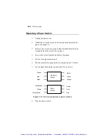
Страница 163: ...he switch from the backside of the panel 5 Push in the replacement switch 6 Put the colored wire plugs on the switch per Figure C 6 below 7 Put the panel back in place and reattach the six screws Auxiliary Switch Brown Blue Black White Yellow Orange Main Switch White Black Purple White Brown Green Gray Red Figure C 11 Colored connections to power switches 8 Plug the power cord in Artisan Technolog...

Страница 164: ...ecial tool remove the colored wire male plugs from the black plastic 5 If necessary unsolder the unshielded ground wire 6 Cut off the cable to remove the damaged break in the wires 7 Put ends on the colored wires 8 Put the colored wire plugs on the switch per Figure C 7 below 9 If needed re solder the ground wire to the silvered metallic end of the connector 10 Put the black shrink wrap cover back...

Страница 165: ...ide Brown Pink Blue Red white Yellow Black Red Orange White 9 8 1 7 6 5 4 3 2 Figure C 12 Colored connections to the mouse cable Artisan Technology Group Quality Instrumentation Guaranteed 888 88 SOURCE www artisantg com ...

Страница 166: ...e cable 4 Remove the solder from the wires 5 Cut off the cable to remove the damaged break in the wires 6 Solder the ends of the colored wires on the plugs of the switch per Figure C 8 below 7 Replace the black protective covering on the wire ends 8 Put the black shrink wrap cover back on or use electrical tape 9 Reattach the connector to the panel 10 Put the panel back in place and reattach the s...

Страница 167: ... to give more room to grab the bulb 3 Using the pliers grab the white plastic part of the bulb unit and pull it out Do not pull on the light bulb itself as it might break 4 Insert a new light bulb unit with careful attention to inserting the two legs of the light bulb into the slits 5 Push the colored plastic light bulb cover back into place Artisan Technology Group Quality Instrumentation Guarant...

Страница 168: ...ddresses with one for the Internal Address Register IAR and the other for Data Both are read and write The board base address can be set to one of the following values 1 178 178 IAR 17A Data 2 17C 17C IAR 17E Data 3 578 578 IAR 57A Data 4 57C 57C IAR 57E Data The IAR register is used to select and enable one of the buffer internal registers These are 16 bit registers that are used to assign resour...

Страница 169: ...his mode emits lower levels of noise PG Power Good status These bits are read only Bit 4 is power good of the controller side right side Bit 5 is power good of the AUX side Left side Bit 6 is System Ready for the GTXI with expanders IAE Internal Address Enable 0 IA disabled default 1 IA enabled If this bit is cleared then no internal register can be accessed IA Internal Address Bit 0 is LSB as fol...

Страница 170: ...ivides this space into blocks Some of these blocks can be assigned to the GTXI by writing to the IOM0 and IOM1 registers The power up default I O space is addresses 200 23Fh and 300 33Fh I O Mask Register 0 IOM0 Internal address IA is 0 Bit 15 12 11 0 Function U IOE11 IOE0 Table D 3 I O Mask Register 0 Bit Functions U Unused IOE I O block enable 0 block disabled 1 block enabled See the table on th...

Страница 171: ...owing table describes the blocks and bit assignments in the IOM0 and IOM1 registers Address Range Purpose Available to GTXI platform Default IOM0 or IOM1 Bit 000 0FF CPU internal resources NO N A 100 177 YES CPU 1 0 178 17F GTXI buffer extender NO N A 180 1EF YES CPU 1 1 1F0 1FF Hard Disk YES CPU 1 8 200 207 Game Port YES GTXI 1 2 208 237 YES GTXI 1 3 238 23F Bus Mouse YES GTXI 1 4 240 25F YES CPU...

Страница 172: ... CPU 0 6 300 31F Prototype YES GTXI 1 5 320 33F YES GTXI 1 6 340 35F YES CPU 1 7 360 377 YES CPU 1 9 378 37F LPT1 YES CPU 1 9 380 39F SDLC 2 YES CPU 0 8 3A0 3AF SDLC 1 YES CPU 0 9 3B0 3DF LPT3 Monochrome EGA CGA YES CPU 0 10 3E0 3EF COM3 YES CPU 0 11 3F0 3F7 Floppy YES CPU 1 10 3F8 3FF COM1 YES CPU 1 11 Table D 5 I O Addresses Artisan Technology Group Quality Instrumentation Guaranteed 888 88 SOUR...

Страница 173: ... Bit 15 8 7 0 Function U A23 A16 Table D 6 Memory Register MSA Bit Functions U Unused Axx These bits correspond to ISA address bits 23 16 and define the first address of the user defined memory block MEMS0 The address can be calculated by multiplying the value in bits 0 7 by 64KB The default value for these bits is all 0 s Memory End Address Register MEA Internal address IA is 3 Bit 15 8 7 0 Funct...

Страница 174: ...ignals are always enabled through the GTXI buffer In the effective mode those signals are enabled only when a GTXI assigned resource is accessed In this mode the noise generated by the GTXI is reduced MSE Memory Block Enable 0 block disabled 1 block enabled See the table below for bit assignments The default value of these bits is 0 all disabled The last block is user defined and is defined by wri...

Страница 175: ...s NO N A 0D000 0D7FF MEMS2 YES CPU 2 0D800 0DFFF MEMS3 YES CPU 3 0E000 0E7FF MEMS4 YES CPU 4 0E800 0EFFF MEMS5 YES CPU 5 0F000 0FFFF BIOS NO N A MSA MEA MEMS0 MEMS1 YES CPU 0 1 Table D 9 Memory Mask Register Addresses Artisan Technology Group Quality Instrumentation Guaranteed 888 88 SOURCE www artisantg com ...

Страница 176: ...A is 5 Bit 15 8 7 5 4 3 0 Function U DE7 DE5 U DE3 DE0 Table D 10 DMA Mask Register Bit Functions U Unused DExx DMA Channel Enable 0 DMA disabled 1 DMA enabled See table below for bit assignments The default value for bits 15 0 is 0000h all disabled The following table describes the DMA channels and their corresponding bits in the DMR register Artisan Technology Group Quality Instrumentation Guara...

Страница 177: ... Spare YES N A 0 1 SDLC YES CPU 1 2 Floppy YES CPU 2 3 LAN YES CPU 3 4 Reserved NO CPU 4 5 Spare YES CPU 5 6 Spare YES CPU 6 7 Spare YES CPU 7 Table D 11 DMA Channel Descriptions Artisan Technology Group Quality Instrumentation Guaranteed 888 88 SOURCE www artisantg com ...

Страница 178: ...nal address IA is 6 Bit 15 11 10 0 Function U IQE10 IQE0 Table D 12 IRQ Mask Register Bit Functions U Unused IQE IRQ channel enable 0 IRQ disabled 1 IRQ enabled See table below for bit assignments The default value for bits 15 0 is 0000h all disabled The following table describes IRQ channels and their corresponding bits in the DMR register Artisan Technology Group Quality Instrumentation Guarante...

Страница 179: ...arallel 2 YES CPU 6 2 6 Floppy YES CPU 6 3 7 Parallel 1 YES CPU 6 4 9 Reserved YES CPU 6 5 10 Spare YES CPU 6 6 11 Spare YES CPU 6 7 12 Spare YES CPU 6 8 14 Hard Disk YES CPU 6 9 15 Spare YES CPU 6 10 Table D 13 IRQ Channel Descriptions Artisan Technology Group Quality Instrumentation Guaranteed 888 88 SOURCE www artisantg com ...

Страница 180: ...nel is designed to provide a link from GTXI instrument board connectors to a Cannon Connector receiver The GTXI 750 provides access to 468 digital and audio range signals The maximum current allowed is 3 Amps per signal Figure E 1 GTXI with Cannon ITT Interface shown Artisan Technology Group Quality Instrumentation Guaranteed 888 88 SOURCE www artisantg com ...

Страница 181: ...erface Specification Number of Connector Blocks 3 Pins per block 156 pins per block Current Rating 3A Voltage DWV 250 VAC RMS Durability 10 000 Cycles Contact Resistance 15 milliohm max Insulation Resistance 5000 Mohm Wiring Accommodation AWG 18 32 Table E 1 GTXI 750 Interface Specification Artisan Technology Group Quality Instrumentation Guaranteed 888 88 SOURCE www artisantg com ...

Страница 182: ...unit needs to be returned to Geotest 3 Read the packing list to ensure that all items listed are enclosed including hardware power cords manuals etc 4 Inspect the unit If any missing items defects or damage are noticed notify Geotest immediately 5 If extra screws and or cables are required refer to the accessory parts list Geotest Part Qty Part Type Description GTXI 751 1 ITA Kit Connector Pins Co...

Страница 183: ...TXI Interface Door 1 Align the three holes on the hinge and place the new door on the front of the GTXI platform 2 Reinstall the screws being careful not to tighten any screw completely until all screws are inserted Connect the Cables Note Depending on the boards ordered with the GTXI consult the GTXI interface specifications to determine the maximum current ratings Design the connections so they ...

Страница 184: ... P2 and or P3 4 GT20 Connect GT20 cable s from the GT20 board s to P1 P2 and or P3 5 HEADER PINS Connect Header connectors to specialized measurement boards according to your requirements Refer to the section Cannon GTXI 750 Pin Out Listing on page 171 to determine the header to ITA connections On the GTXI 750 the header connectors are J1 J2 J3 JP1 JP2 JP3 and JP4 Artisan Technology Group Quality ...

Страница 185: ...pe Areas The Cannon ITT interface panel has four prototype areas for the user s own needs Each prototype area has a common column of pins labeled GND all of which are connected to an internal ground plane There is also a common column of pins labeled V which in a given prototype area are all connected to each other The V pins on separate prototype areas are not connected to each other Users can us...

Страница 186: ...g pins need to be known The following listing aids development efforts J4 J7 Pin 50 Pin 2 Pin 1 Pin 49 Pin 1 GND Pin 2 Pin 25 Pin 26 J1 J3 P1 P3 JP1 JP3 Pin 78 Pin 20 Pin 40 Pin 1 Pin 1 GND Pin 2 Pin 1 GND Connector Designations and Locations Figure E 3 GTXI 750 Connector Designation component side Artisan Technology Group Quality Instrumentation Guaranteed 888 88 SOURCE www artisantg com ...

Страница 187: ...rea C Prototype Area B Prototype Area A Pin A 1 Pin C_1 6 Pin A 1 Pin C_1 6 Pin A 1 Pin C_1 6 V GND GND V V GND GND V Figure E 4 GTXI 750 Connector Locations component side Artisan Technology Group Quality Instrumentation Guaranteed 888 88 SOURCE www artisantg com ...

Страница 188: ...2 P1 57 P2 28 P1 18 P2 24 P1 56 M P1 59 JP1 11 P1 20 JP1 9 P1 78 JP1 7 P1 58 JP1 5 P1 39 JP1 3 P1 19 JP1 1 N P2 22 P2 2 P2 60 P2 40 P2 21 P2 1 P P2 62 P2 42 P2 23 P2 3 P2 61 P2 41 R P2 25 P2 5 P2 63 P2 43 P2 24 P2 4 S P2 65 P2 45 P2 26 P2 6 P2 64 P2 44 T P2 28 P2 8 P2 66 P2 46 P2 27 P2 7 U P2 68 P2 48 P2 29 P2 9 P2 67 P2 47 V P2 31 P2 11 P2 69 P2 49 P2 30 P2 10 W P2 71 P2 51 P2 32 P2 12 P2 70 P2 5...

Страница 189: ...8 P3 76 P3 56 M P3 59 JP3 11 P3 20 JP3 9 P3 78 JP3 7 P3 58 JP3 5 P3 39 JP3 3 P3 19 JP3 1 N J3 2 J3 1 J2 2 J2 1 J1 2 J1 1 P J3 4 J3 3 J2 4 J2 3 J1 4 J1 3 R J3 6 J3 5 J2 6 J2 5 J1 6 J1 5 S J3 8 J3 7 J2 8 J2 7 J1 8 J1 7 T J3 10 J3 9 J2 10 J2 9 J1 10 J1 9 U J3 12 J3 11 J2 12 J2 11 J1 12 J1 11 V J3 14 J3 13 J2 14 J2 13 J1 14 J1 13 W J3 16 J3 15 J2 16 J2 15 J1 16 J1 15 X J3 18 J3 17 J2 18 J2 17 J1 18 J1...

Страница 190: ... K J5 34 J5 33 J5 32 J5 49 J5 30 J5 29 L J5 50 J5 40 J5 39 J5 38 J5 37 J5 35 M GND GND GND GND GND GND N GND GND GND GND GND GND P J6 8 J6 7 J6 5 J6 4 J6 3 J6 2 R J6 14 J6 13 J6 12 J6 47 J6 10 J6 9 S J6 48 J6 20 J6 19 J6 18 J6 17 J6 15 T J6 28 J6 27 J6 25 J6 24 J6 23 J6 22 U J6 34 J6 33 J6 32 J6 49 J6 30 J6 29 V J6 50 J6 40 J6 39 J6 38 J6 37 J6 35 W J7 7 J7 5 J7 4 J7 3 J7 2 GND X J7 14 J7 13 J7 12...

Страница 191: ...176 GTXI User s Guide Artisan Technology Group Quality Instrumentation Guaranteed 888 88 SOURCE www artisantg com ...

Страница 192: ... a link from GTXI instrument board connectors to a Virginia panel receiver The GTXI 760 offers the use a variety of signals such as digital analog and RF 500 MHz It also has a high current capacity of 20 Amp per signal Figure F 1 GTXI with Virginia Panel Interface shown Artisan Technology Group Quality Instrumentation Guaranteed 888 88 SOURCE www artisantg com ...

Страница 193: ...nals on Block 1 8 high current pins optional Block 2 16 high frequency pins Block 2 Current Rating Standard Pins High Current Pins 2A 20A Voltage 250 VAC RMS Durability 10 000 Cycles Contact Resistance Standard Pins High Current Pins 10 mOhm 2 3 mOhm Insulation Resistance 5000 MOhm Wiring Accommodation Standard Pins High Current Pins AWG 14 max AWG 8 max Bandwidth Standard Pins High Frequency Pins...

Страница 194: ... to Geotest 3 Read the packing list to ensure that all items listed are enclosed including hardware power cords manuals etc 4 Inspect the unit If any missing items defects or damage are noticed notify Geotest immediately 5 If extra screws and or cables are required refer to the accessory parts list Geotest Part Qty Part Type Description GTXI 761 1 ITA Kit Module Pins Cover GTXI 762 100 Pins ITA Co...

Страница 195: ...I Interface Door 1 Align the three holes on the hinge and place the new door on the front of the GTXI platform 2 Reinstall the screws being careful not to tighten any one screw completely until all screws are inserted Connect the Cables Note Depending on the boards ordered with the GTXI consult the GTXI interface specifications to determine the maximum current ratings Design the connections so the...

Страница 196: ...rent GT20 connection to P1 P2 or P3 on the Virginia 760 Interface Panel Use only P4 5 HEADER PINS Connect Header connectors to specialized measurement boards according to your requirements Refer to the section Virginia GTXI 760 Pin Out Listing on page 184 to determine the header to ITA connections On the GTXI 760 the header connectors are J1 J2 and J11 6 Power Coax Connector Design and build custo...

Страница 197: ...in this manual and the manual that came with the Virginia interface To install 1 Design and build the Virginia Panel Company ITA Interchangeable Test Adapter interface to meet the needs of the appropriate DUT Device Under Test using the GTXI 761 GTXI 760 ITA Kit 2 Connect the appropriate wires from the DUT to the Virginia Panel ITA GTXI 761 interface that was built 3 Remove the black metal cover p...

Страница 198: ...nterface to the panel on the front of the GTXI door 5 Close the latch This presses the Virginia Panel receiver against the PCB golden plated pads for a bed of nails type of interface Artisan Technology Group Quality Instrumentation Guaranteed 888 88 SOURCE www artisantg com ...

Страница 199: ...ins need to be known The following listing aids development efforts J3 J7 Pin 1 Pin 49 Pin 50 Pin 2 Pin 8 Pin 8a 8b Pin 1 Pin 1a 1b J8 J9 P1 P4 J1 J2 J11 Pin 1 Pin 40 Pin 20 Pin 78 Pin 1 GND Pin 20 Pin 2 Pin 19 Figure F 3 GTXI 760 Connector Designations and Locations Artisan Technology Group Quality Instrumentation Guaranteed 888 88 SOURCE www artisantg com ...

Страница 200: ...a Panel Interface 185 VP1 VP2 Pin K 38 Pin A 1 Pin A 1 Pin K 22 High Current Pins Figure F 4 GTXI 760 Connector Locations component side Artisan Technology Group Quality Instrumentation Guaranteed 888 88 SOURCE www artisantg com ...

Страница 201: ...P3 16 P3 14 P3 12 P3 10 P3 8 P3 6 P3 4 P3 2 19 GND P3 37 P3 35 P3 33 P3 31 P3 29 P3 27 P3 25 P3 23 P3 21 20 GND P3 38 P3 36 P3 34 P3 32 P3 30 P3 28 P3 26 P3 24 P3 22 21 GND P3 56 P3 54 P3 52 P3 50 P3 48 P3 46 P3 44 P3 42 P3 40 22 GND P3 57 P3 55 P3 53 P3 51 P3 49 P3 47 P3 45 P3 43 P3 41 23 GND P3 76 P3 74 P3 72 P3 70 P3 68 P3 66 P3 64 P3 62 P3 60 24 GND P3 77 P3 75 P3 73 P3 71 P3 69 P3 67 P3 65 P3...

Страница 202: ... J7 3 J7 4 J7 5 J7 7 J7 8 J7 9 J7 10 J7 47 GND 12 J6 32 J6 33 J6 34 J6 35 J6 37 J6 38 J6 39 J6 40 J6 50 GND 11 J6 22 J6 23 J6 24 J6 25 J6 27 J6 28 J6 29 J6 30 J6 49 GND 10 J6 12 J6 13 J6 14 J6 15 J6 17 J6 18 J6 19 J6 20 J6 48 GND 9 J6 2 J6 3 J6 4 J6 5 J6 7 J6 8 J6 9 J6 10 J6 47 GND 8 J5 32 J5 33 J5 34 J5 35 J5 37 J5 38 J5 39 J5 40 J5 50 GND 7 J5 22 J5 23 J5 24 J5 25 J5 27 J5 28 J5 29 J5 30 J5 49 G...

Страница 203: ... J9 4A B J8 5B J8 6B J9 7B J9 8B J8 5 J8 6 J9 7 J9 8 A J8 5A J8 6A J9 7A J9 8A B J8 1B J8 2B J8 3B J8 4B J8 1 J8 2 J8 3 J8 4 A J8 1A J8 2A J8 3A J8 4A B A B A B A B A Table F 5 Connector VP2 bottom Artisan Technology Group Quality Instrumentation Guaranteed 888 88 SOURCE www artisantg com ...

Страница 204: ...18 99 Mouse 55 C Cable tray 25 36 37 Cabling 38 Carrier board 14 52 54 56 illustration of 58 Carrier Board 5 CGA 157 Chassis Instrument Controllers 131 CMDIALOG VBX 102 Collar screw 139 COM1 55 COM2 55 COM3 55 COM4 55 Common bus 86 87 90 93 94 Comparing the GTXI 700 and GT7700 6 CONFIG SYS 32 38 49 85 Conflicts 55 Controller 9 33 illustrated 19 Isolation 18 Cooling 6 22 25 128 CPU 20 Modules and A...

Страница 205: ...In GTPC 4 IRQ Channels 164 G Game port I O base addresses 55 GPIB 3 4 7 25 55 GT7020 I O addresses 64 I O base address 66 75 switch assignments 65 74 GT7021 I O addresses 73 GT7700 Overview of 4 Slots 16 GT7710 System Block Diagram 13 GTPC components 129 GTPC 7586 9 assigning resources 33 38 Buffer Board 18 connected to two GTXI 46 connections on front 37 installing 33 Overview of 4 using with mul...

Страница 206: ...and 102 H Hard disk I O address 156 I O base address 55 IRQ channel 164 Hard Disk in GTPC 4 Hardware buffering 99 Hexadecimal to binary 66 75 Host computer connected to multiple GTXI 47 I I O Addresses View 111 base address 153 base addresses on carrier boards56 base addresses on instrument boards 55 IDE Controller 129 IEEE 488 3 7 25 Input Output 51 52 Inspecting the GTXI 27 Installing GT7700 30 ...

Страница 207: ...r on carrier board 23 88 93 connector pin out 89 94 connector connecting to 87 using with GT7720 92 LPT1 32 55 LPT2 55 LPT3 55 M MacPanel 25 Main switch 49 MEM Avoiding Conflicts 52 Memory Addresses View 113 manager 85 pre defined 84 158 MEMS0 MEMS1 84 Monitor 32 37 Motherboard 139 Mouse 146 149 cable replacing on GTPC 146 connecting to GT7700 31 connecting to GTXI 700 34 Multiple GTXI Platform 44...

Страница 208: ...40 SEL1 39 40 Selecting line voltage 28 41 Separate Power Supplies 21 Serial port 25 Setting Up the GTXI 27 Setup exe 42 Slave 46 47 GTXI used as 45 47 motherboard part number 139 Slot 13 controlled by main switch 49 Spare parts list 139 Stand alone mode installing GTXI 700 33 Sub bus 95 Suspending operation of instrument platform 49 SVGA 4 SW1 57 58 60 64 73 SW2 57 64 73 T Toolbar 111 113 116 GTX...

Страница 209: ...Chapter 3 Index 194 Artisan Technology Group Quality Instrumentation Guaranteed 888 88 SOURCE www artisantg com ...

Страница 210: ...l service in house repair center WE BUY USED EQUIPMENT Sell your excess underutilized and idle used equipment We also offer credit for buy backs and trade ins www artisantg com WeBuyEquipment REMOTE INSPECTION Remotely inspect equipment before purchasing with our interactive website at www instraview com LOOKING FOR MORE INFORMATION Visit us on the web at www artisantg com for more information on ...

Отзывы: