


170
GTXI User's Guide
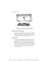
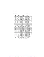
Figure E-2: Typical GTXI Cannon Interface Door
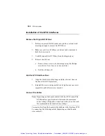
Configure and Install the Interface
Instructions for configuring the interface panel to the Cannon ITT
connectors are beyond the scope of this manual. Users build ITT
interfaces to meet specific needs. Refer to the tables in this manual
and the literature that came with the Cannon interface.
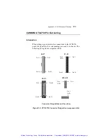
Prototype Areas
The Cannon ITT interface panel has four prototype areas for the
user’s own needs. Each prototype area has a common column of
pins labeled ‘GND,’ all of which are connected to an internal
ground plane. There is also a common column of pins labeled ‘V,’
which in a given prototype area are all connected to each other. The
V pins on separate prototype areas are not connected to each other.
Users can use the prototype areas to configure the board to their
specific applications.
Artisan Technology Group - Quality Instrumentation ... Guaranteed | (888) 88-SOURCE | www.artisantg.com
Содержание Geotest GT7700
Страница 113: ...98 GTXI User s Guide Artisan Technology Group Quality Instrumentation Guaranteed 888 88 SOURCE www artisantg com ...
Страница 139: ...Artisan Technology Group Quality Instrumentation Guaranteed 888 88 SOURCE www artisantg com ...
Страница 145: ...Artisan Technology Group Quality Instrumentation Guaranteed 888 88 SOURCE www artisantg com ...
Страница 191: ...176 GTXI User s Guide Artisan Technology Group Quality Instrumentation Guaranteed 888 88 SOURCE www artisantg com ...
Страница 209: ...Chapter 3 Index 194 Artisan Technology Group Quality Instrumentation Guaranteed 888 88 SOURCE www artisantg com ...