6600-NG User’s Manual
125-9110A
Page 77
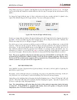
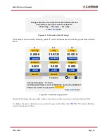
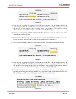
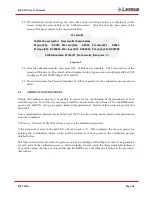
Figure 6.3 : Calibration (Main)
Connect the differential-pressure output (QcinHg) of the Pressure Standard to the Pt output of the 6600-
NG. Connect the absolute-pressure output (PsinHg) of the Pressure Standard to the Ps1 and Ps2 outputs
of the 6600-NG. (The Ps1 and Ps2 outputs can be internally connected together by opening the Ps2 Vent
valve while keeping the Ps2 output closed)
The calibration adjustment requires generating two differential pressures at the Pt output and two
absolute pressures at the Ps1 & Ps2 outputs. The details are provided in Section 6.4 below. The
verification and entry of non-linearity offsets (if required) requires generating pressures in 10%
increments of the full-scale pressure for each output. The details are provided in Section 6.5 below.
6.4
CALIBRATION PROCEDURE
The step-by-step procedure for calibrating the 6600-NG is provided below. The assumption made is that
the Pressure Standard can generate differential pressures (QcinHg) for the Pt output of the 6600-NG and
can simultaneously generate absolute pressures (PsinHg) for the Ps1 and Ps2 outputs of the 6600-NG.
The sample calibration report shown in Figure 6.10 (at the end of this Section) will be referenced in the
procedure below.
1.
Set up the 6600-NG as detailed in Section 6.3.
2.
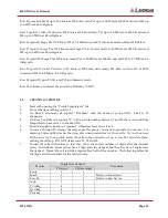
Keep QcinHg=0 and exercise PsinHg between 1.6 inHg and 38 inHg, three times. This will purge
the system with clean Dry Air.
3.
Generate exactly QcinHg=0.0000 and PsinHg=1.6000. Wait for a minimum of 5 minutes to allow
temperature effects to stabilize.
4.
Note (on the calibration report, not on the Remote unit) the 6600-NG’s Ps1 and Ps2 Actual values
as the “As Found” values for the Ps1 and Ps2 vacuum point. (See Figure 6.10)
5.
Press ‘
3
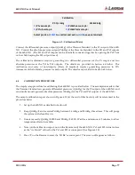
’ on the Remote to enter the ‘Ps1&2’ vacuum point. The screen will appear as follows.
Calibration
Pt: Qc inHg
Ps1&2 inHg
1)
Pt vacuum pt.:
3)
Ps1&2 vacuum pt.:
2)
Pt full-scale pt.:
4)
Ps1&2 full-scale pt.:
Select point, or
CANC
to void cal and exit, or
GO
to save cal and exit


