


74
Hydraulic System
For new vehicles, change the return filter element after 50
hours of use, and twice a year
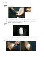
afterwards or when the filter restriction indicator is in red (see Figure 5-1), whichever comes first
(see
Clean the strainer inside the hydraulic tank after the first 50
hours of use, and twice a year
afterwards or when the filter restriction indicator is in red (see Figure 5-1), whichever comes first
(see
Hydraulic oil must be replaced at least once a year, or when contaminated (see
N
OTE
:
The ball valve on the hydraulic tank must be completely open before engaging the pump or
starting the engine.
Labrie Enviroquip Group requires that the hydraulic fluid and return oil filter be changed and that the
strainer be cleaned before changing the hydraulic pump.
Manufacturer’s warranty on hydraulic pumps provided or sold by Labrie Enviroquip Group could be
declared void if the hydraulic fluid and return oil filter are not changed, and if the strainer is not
cleaned prior to replacing the hydraulic pump.
Therefore, it is mandatory to change the return oil filter and clean the strainer after the
first
50
hours
of pump operation, then twice a year or when the filter restriction indicator is in red (see Figure 5-1),
whichever comes first. The hydraulic fluid must be changed once a year. Hydraulic fluid
contamination will severely damage hydraulic components.
Figure 5-1 Filter restriction indicator
Inspecting Hydraulic Oil
Inspecting hydraulic oil is a very important maintenance task that must be done as per your
Preventive
Maintenance Chart
. The most important items to look at when inspecting hydraulic oil are:
color
amount
texture (usually in the form of air bubbles or foam) and
Содержание MINIMAX
Страница 1: ...MINIMAX TM MAINTENANCE MANUAL...
Страница 2: ......
Страница 3: ...MINIMAX MAINTENANCE MANUAL...
Страница 8: ...vi Table of Contents Adjusting Arm Speed 164...
Страница 30: ...22 Safety Figure 2 17 Drain valve on air tank...
Страница 72: ...64 Lubrication Figure 4 10 Lubrication chart Helping Hand arm...
Страница 80: ...72 Lubrication...
Страница 90: ...82 Hydraulic System Figure 5 8 Oil temp level gauge Figure 5 9 Steel hydraulic tank...
Страница 101: ...Hydraulic System 93 Figure 5 20 Hydraulic tank Access panel Return filter Strainer Suction line...
Страница 102: ...94 Hydraulic System Figure 5 21 Strainer assembly Strainer...
Страница 106: ...98 Hydraulic System Figure 5 25 Detecting cylinder internal leaks 1 2 3 4 5 A A A...
Страница 108: ...100 Hydraulic System...
Страница 113: ...Electrical System 105 Electrical Schematics Cab Adaptation...
Страница 114: ...106 Electrical System Cab Console Controls...
Страница 115: ...Electrical System 107 Cab Controller...
Страница 116: ...108 Electrical System Chassis...
Страница 117: ...Electrical System 109 Body Module rear side...
Страница 118: ...110 Electrical System Body Module front side...
Страница 119: ...Electrical System 111 Tailgate Lighting...
Страница 120: ...112 Electrical System Panic Bars Crusher Panel Tipper Interlocks...
Страница 121: ...Electrical System 113 Cameras Switchpack Details Interlocks AUTO 10 SEC INHIBIT AUTO N AUTO ON...
Страница 122: ...114 Electrical System...
Страница 127: ...Troubleshooting 119 Figure 8 4 Ball end hex wrench metric and SAE...
Страница 134: ...126 Troubleshooting Figure 8 6 Tailgate locking mechanism...
Страница 156: ...148 Multiplexing...
Страница 162: ...154 Multiplexing...
Страница 164: ...156 Lifting Arm Figure 10 1 Mounting bolts Figure 10 2 Helping Hand gripper Figure 10 3 Hoses...


