


Multiplexing
151
Figure 9-22 Allison Doc software
If your vehicle ECU needs repair or replacement, or if it needs specific programming parameters, see
Programmed Parameters
below.
Programmed Parameters
Programming in the transmission ECU module affects engine speed,
PTO
engagement and operation,
as well as the (optional) auto-neutral system. If the ECU module is replaced, it must be
reprogrammed to reset the vehicle operating parameters. Refer to Table 5 to reprogram the
transmission ECU.
On chassis supplied by Labrie, the programming package for Allison transmissions is package nº
142.
Some customer chassis may have different programming packages. Refer to your local Allison dealer
for original programming packages. For further information regarding ECU programming, contact
Labrie
Plus
.
This page and the next page show how Allison electronic transmission ECUs are programmed for
Labrie vehicles.
N
OTE
:
The parameters shown in the following tables are typical values and are given for guidance
only. Some vehicles may need different parameters based on the options installed. Please call
Labrie
Plus
for the values that are specific to your vehicle.
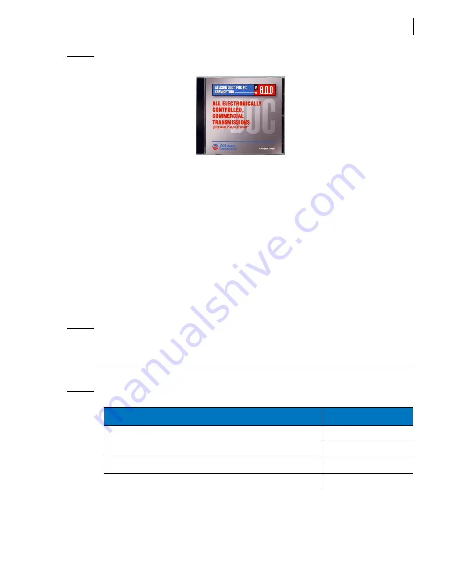
Table 5
Allison transmission programmed parameters (cont’d)
Parameters
r.p.m.
Maximum engine speed for
PTO
engagement
900
Maximum engine speed for
PTO
operation
2,000
Maximum output speed for
PTO
engagement
5,000
Maximum output speed for
PTO
operation
930
a
(15
mph)
Содержание MINIMAX
Страница 1: ...MINIMAX TM MAINTENANCE MANUAL...
Страница 2: ......
Страница 3: ...MINIMAX MAINTENANCE MANUAL...
Страница 8: ...vi Table of Contents Adjusting Arm Speed 164...
Страница 30: ...22 Safety Figure 2 17 Drain valve on air tank...
Страница 72: ...64 Lubrication Figure 4 10 Lubrication chart Helping Hand arm...
Страница 80: ...72 Lubrication...
Страница 90: ...82 Hydraulic System Figure 5 8 Oil temp level gauge Figure 5 9 Steel hydraulic tank...
Страница 101: ...Hydraulic System 93 Figure 5 20 Hydraulic tank Access panel Return filter Strainer Suction line...
Страница 102: ...94 Hydraulic System Figure 5 21 Strainer assembly Strainer...
Страница 106: ...98 Hydraulic System Figure 5 25 Detecting cylinder internal leaks 1 2 3 4 5 A A A...
Страница 108: ...100 Hydraulic System...
Страница 113: ...Electrical System 105 Electrical Schematics Cab Adaptation...
Страница 114: ...106 Electrical System Cab Console Controls...
Страница 115: ...Electrical System 107 Cab Controller...
Страница 116: ...108 Electrical System Chassis...
Страница 117: ...Electrical System 109 Body Module rear side...
Страница 118: ...110 Electrical System Body Module front side...
Страница 119: ...Electrical System 111 Tailgate Lighting...
Страница 120: ...112 Electrical System Panic Bars Crusher Panel Tipper Interlocks...
Страница 121: ...Electrical System 113 Cameras Switchpack Details Interlocks AUTO 10 SEC INHIBIT AUTO N AUTO ON...
Страница 122: ...114 Electrical System...
Страница 127: ...Troubleshooting 119 Figure 8 4 Ball end hex wrench metric and SAE...
Страница 134: ...126 Troubleshooting Figure 8 6 Tailgate locking mechanism...
Страница 156: ...148 Multiplexing...
Страница 162: ...154 Multiplexing...
Страница 164: ...156 Lifting Arm Figure 10 1 Mounting bolts Figure 10 2 Helping Hand gripper Figure 10 3 Hoses...


