


Hydraulic System
81
7.
Start the engine. You can slowly raise the engine RPM only after 5
minutes. When you raise the
RPM, always make sure that the pump does not make excessive noise.
8.
Before putting the vehicle back in service, recalibrate the system pressures.
N
OTE
:
For units equipped with a vane pump.
Inspecting the Hydraulic Tank
Verify that the oil in the tank is clean (not colored) and always at the appropriate level.
To inspect the hydraulic tank:
1.
Lock out and tag out the vehicle (see
Locking Out and Tagging Out the Vehicle
2.
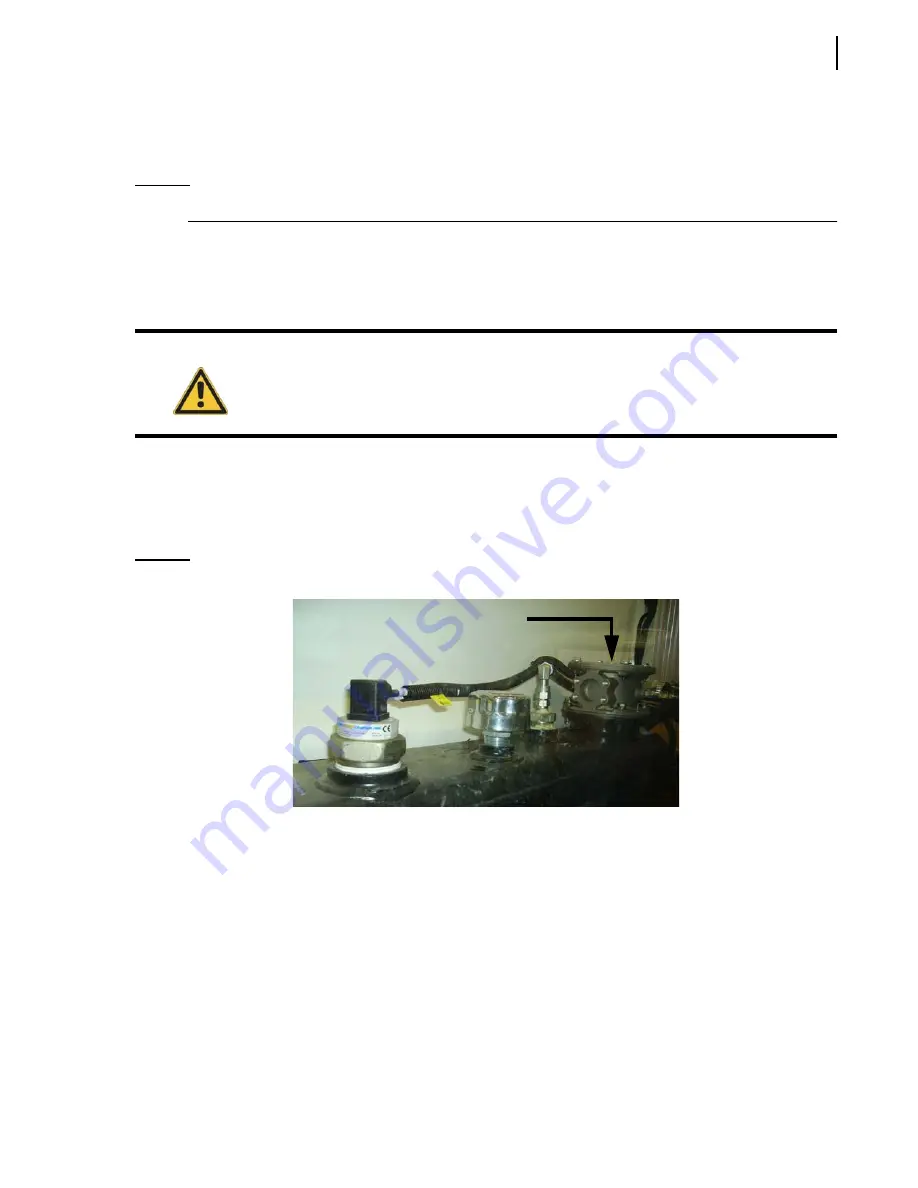
Clean the strainer and replace the filter element inside the tank after the first 50
hours of service
Figure 5-7 Filter housing element
For more information on maintenance schedule, see
3.
Make sure that the filler cap is not obstructed and works properly.
4.
Make sure that the hydraulic oil is clean (not colored) and at least at 3/4 on the oil level gauge
(with all cylinders retracted).
The complete system requires between 50 and 60
gallons of oil.
Caution!
Maximum temperature for hydraulic oil is 77
°C
(180
°F).
Содержание MINIMAX
Страница 1: ...MINIMAX TM MAINTENANCE MANUAL...
Страница 2: ......
Страница 3: ...MINIMAX MAINTENANCE MANUAL...
Страница 8: ...vi Table of Contents Adjusting Arm Speed 164...
Страница 30: ...22 Safety Figure 2 17 Drain valve on air tank...
Страница 72: ...64 Lubrication Figure 4 10 Lubrication chart Helping Hand arm...
Страница 80: ...72 Lubrication...
Страница 90: ...82 Hydraulic System Figure 5 8 Oil temp level gauge Figure 5 9 Steel hydraulic tank...
Страница 101: ...Hydraulic System 93 Figure 5 20 Hydraulic tank Access panel Return filter Strainer Suction line...
Страница 102: ...94 Hydraulic System Figure 5 21 Strainer assembly Strainer...
Страница 106: ...98 Hydraulic System Figure 5 25 Detecting cylinder internal leaks 1 2 3 4 5 A A A...
Страница 108: ...100 Hydraulic System...
Страница 113: ...Electrical System 105 Electrical Schematics Cab Adaptation...
Страница 114: ...106 Electrical System Cab Console Controls...
Страница 115: ...Electrical System 107 Cab Controller...
Страница 116: ...108 Electrical System Chassis...
Страница 117: ...Electrical System 109 Body Module rear side...
Страница 118: ...110 Electrical System Body Module front side...
Страница 119: ...Electrical System 111 Tailgate Lighting...
Страница 120: ...112 Electrical System Panic Bars Crusher Panel Tipper Interlocks...
Страница 121: ...Electrical System 113 Cameras Switchpack Details Interlocks AUTO 10 SEC INHIBIT AUTO N AUTO ON...
Страница 122: ...114 Electrical System...
Страница 127: ...Troubleshooting 119 Figure 8 4 Ball end hex wrench metric and SAE...
Страница 134: ...126 Troubleshooting Figure 8 6 Tailgate locking mechanism...
Страница 156: ...148 Multiplexing...
Страница 162: ...154 Multiplexing...
Страница 164: ...156 Lifting Arm Figure 10 1 Mounting bolts Figure 10 2 Helping Hand gripper Figure 10 3 Hoses...


