


38
General Maintenance
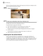
To adjust a proximity switch:
1.
Loosen the proximity switch nuts.
2.
Adjust the proximity switch so that there is a gap of approximetely 3/16
of an inch (4.8
mm)
between the plate (target) and the switch.
3.
Tighten up the nuts.
4.
Test the operation.
The proximity switch light should turn on when the target is detected; if not, repeat the adjustment
procedure.
In the following sections, you will learn how to adjust limit/proximity switches based on the function
for which they are used.
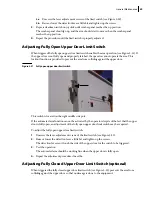
Adjusting Packer Extend Limit/Proximity Switch
Packer limit/proximity switches were adjusted at the factory for optimal packer operation. If the area
behind the packer is not properly cleaned
daily,
limit/proximity switches may no longer stop the
packer or may prevent automatic cycles from working properly.
Furthermore, over time, misalignment of the components may occur due to the frequent back and
forth motion of the packer. An adjustment might be necessary to prevent cylinders from completely
extending and retracting to the end of their strokes.
On some units, the packer range of motion is controlled by two limit switches and on other units, it is
controlled by a set of one limit switch and one proximity switch. The limit/proximity switch that
stops the packer during extension (packer extend) is located near the hopper floor, on the curbside,
just under the automated arm housing (see Figure 3-22). The limit switch that stops the packer
during retraction (packer retract) is located on front right-hand side hopper corner, behind the cab
(see Figure 3-23).
Danger!
Always lock out and tag out the vehicle when inspecting it or performing maintenance
on it (see
Locking Out and Tagging Out the Vehicle
.
Содержание MINIMAX
Страница 1: ...MINIMAX TM MAINTENANCE MANUAL...
Страница 2: ......
Страница 3: ...MINIMAX MAINTENANCE MANUAL...
Страница 8: ...vi Table of Contents Adjusting Arm Speed 164...
Страница 30: ...22 Safety Figure 2 17 Drain valve on air tank...
Страница 72: ...64 Lubrication Figure 4 10 Lubrication chart Helping Hand arm...
Страница 80: ...72 Lubrication...
Страница 90: ...82 Hydraulic System Figure 5 8 Oil temp level gauge Figure 5 9 Steel hydraulic tank...
Страница 101: ...Hydraulic System 93 Figure 5 20 Hydraulic tank Access panel Return filter Strainer Suction line...
Страница 102: ...94 Hydraulic System Figure 5 21 Strainer assembly Strainer...
Страница 106: ...98 Hydraulic System Figure 5 25 Detecting cylinder internal leaks 1 2 3 4 5 A A A...
Страница 108: ...100 Hydraulic System...
Страница 113: ...Electrical System 105 Electrical Schematics Cab Adaptation...
Страница 114: ...106 Electrical System Cab Console Controls...
Страница 115: ...Electrical System 107 Cab Controller...
Страница 116: ...108 Electrical System Chassis...
Страница 117: ...Electrical System 109 Body Module rear side...
Страница 118: ...110 Electrical System Body Module front side...
Страница 119: ...Electrical System 111 Tailgate Lighting...
Страница 120: ...112 Electrical System Panic Bars Crusher Panel Tipper Interlocks...
Страница 121: ...Electrical System 113 Cameras Switchpack Details Interlocks AUTO 10 SEC INHIBIT AUTO N AUTO ON...
Страница 122: ...114 Electrical System...
Страница 127: ...Troubleshooting 119 Figure 8 4 Ball end hex wrench metric and SAE...
Страница 134: ...126 Troubleshooting Figure 8 6 Tailgate locking mechanism...
Страница 156: ...148 Multiplexing...
Страница 162: ...154 Multiplexing...
Страница 164: ...156 Lifting Arm Figure 10 1 Mounting bolts Figure 10 2 Helping Hand gripper Figure 10 3 Hoses...


