


General Maintenance
49
2 a.
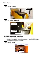
Unscrew the lever adjustement screws of the limit switch (see Figure 3-30).
2 b.
Raise or lower the detection lever a little bit and tighten up the screws.
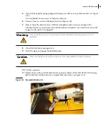
3.
Depress deadman switch on joystick until crusher panel reaches the up position.
The crusher panel should go up, and the arm should start to move when the crusher panel
reaches the up position.
4.
Repeat the procedure until the limit switch is properly adjusted.
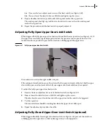
Adjusting Fully Open Upper Door Limit Switch
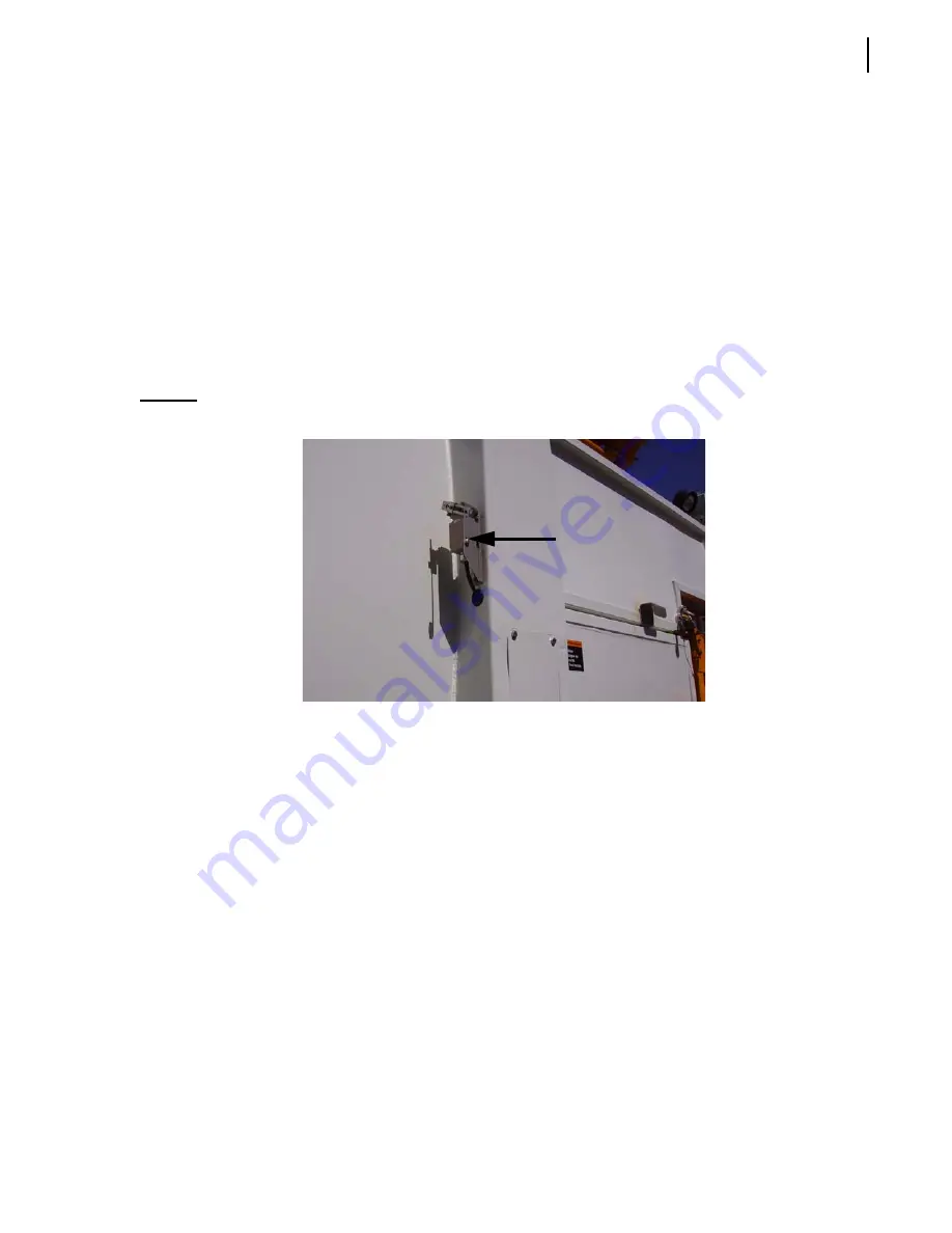
When triggered the fully open upper door limit switch enables the arm operation (see Figure 3-31). If
the upper door is not fully open and properly latched, the operator cannot operate the arm. This
lockout function is provided to prevent the arm from colliding against the upper door.
Figure 3-31 Fully open upper door limit switch
This switch is located on the right middle side post.
If the automated arm function cannot be activated by the operator despite of the fact that the upper
door is fully open, an adjustment of the fully open upper door limit switch may be required.
To adjust the fully open upper door limit switch:
1.
Unscrew the lever adjustement screws of the limit switch (see Figure 3-30).
2.
Raise or lower the detection lever a little bit and tighten up the screws.
The detection lever must touch the side of the upper door for the switch to be triggered.
3.
Test the operation.
The automated arm should be working fine when the upper door is fully open.
4.
Repeat the adjustment procedure if need be.
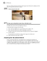
Adjusting Fully Closed Upper Door Limit Switch (optional)
When triggered the fully closed upper door limit switch (see Figure 3-32) prevents the arm from
colliding against the upper door so that no damage is done to the equipment.
Содержание MINIMAX
Страница 1: ...MINIMAX TM MAINTENANCE MANUAL...
Страница 2: ......
Страница 3: ...MINIMAX MAINTENANCE MANUAL...
Страница 8: ...vi Table of Contents Adjusting Arm Speed 164...
Страница 30: ...22 Safety Figure 2 17 Drain valve on air tank...
Страница 72: ...64 Lubrication Figure 4 10 Lubrication chart Helping Hand arm...
Страница 80: ...72 Lubrication...
Страница 90: ...82 Hydraulic System Figure 5 8 Oil temp level gauge Figure 5 9 Steel hydraulic tank...
Страница 101: ...Hydraulic System 93 Figure 5 20 Hydraulic tank Access panel Return filter Strainer Suction line...
Страница 102: ...94 Hydraulic System Figure 5 21 Strainer assembly Strainer...
Страница 106: ...98 Hydraulic System Figure 5 25 Detecting cylinder internal leaks 1 2 3 4 5 A A A...
Страница 108: ...100 Hydraulic System...
Страница 113: ...Electrical System 105 Electrical Schematics Cab Adaptation...
Страница 114: ...106 Electrical System Cab Console Controls...
Страница 115: ...Electrical System 107 Cab Controller...
Страница 116: ...108 Electrical System Chassis...
Страница 117: ...Electrical System 109 Body Module rear side...
Страница 118: ...110 Electrical System Body Module front side...
Страница 119: ...Electrical System 111 Tailgate Lighting...
Страница 120: ...112 Electrical System Panic Bars Crusher Panel Tipper Interlocks...
Страница 121: ...Electrical System 113 Cameras Switchpack Details Interlocks AUTO 10 SEC INHIBIT AUTO N AUTO ON...
Страница 122: ...114 Electrical System...
Страница 127: ...Troubleshooting 119 Figure 8 4 Ball end hex wrench metric and SAE...
Страница 134: ...126 Troubleshooting Figure 8 6 Tailgate locking mechanism...
Страница 156: ...148 Multiplexing...
Страница 162: ...154 Multiplexing...
Страница 164: ...156 Lifting Arm Figure 10 1 Mounting bolts Figure 10 2 Helping Hand gripper Figure 10 3 Hoses...


