9
Multiplexing
As Labrie Enviroquip Group vehicles become more
and more efficient, they require more automation
features and thus some programming. Currently,
M
INIMAX
™ vehicles require programming of:
Labrie’s CAN bus-based multiplexed system
the Allison transmission parameters, and
the Cummins engine parameters
The following pages provide the necessary
information for these tasks.
Labrie’s Multiplexed System
Labrie has equipped your M
INIMAX
™ unit with a CAN
bus-based multiplexed system, which integrates a
display monitor, a rocker switch panel, a joystick, and
three IFM electronic controllers. This whole system
has been designed to help you operate your unit in an
efficient and easy way. Labrie’s multiplexed system is
reliable and safe and it requires less wiring harnesses to
operate. It can also monitor various function status of
the body and display warning and caution messages.
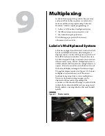
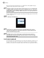
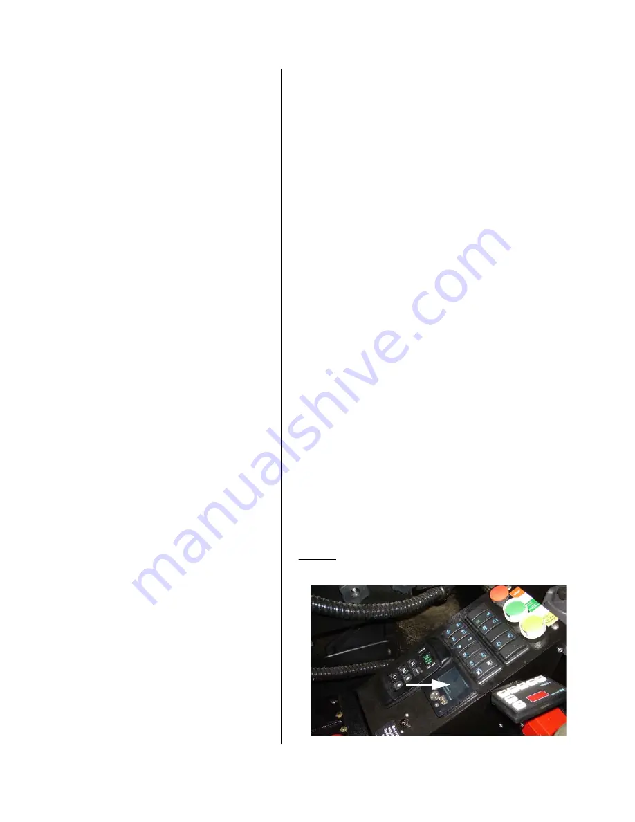
Through its display monitor (see Figure 9-1), Labrie’s
multiplexed system informs you of the various
functions being carried out or of any malfunctions.
Various caution and warning messages can be
displayed on the monitor, depending of the
seriousness of the situation. Messages in yellow blocks
indicate that caution should be used; messages in red
blocks indicate a warning situation that must be dealt
quickly.
Figure 9-1 Display monitor
Содержание MINIMAX
Страница 1: ...MINIMAX TM MAINTENANCE MANUAL...
Страница 2: ......
Страница 3: ...MINIMAX MAINTENANCE MANUAL...
Страница 8: ...vi Table of Contents Adjusting Arm Speed 164...
Страница 30: ...22 Safety Figure 2 17 Drain valve on air tank...
Страница 72: ...64 Lubrication Figure 4 10 Lubrication chart Helping Hand arm...
Страница 80: ...72 Lubrication...
Страница 90: ...82 Hydraulic System Figure 5 8 Oil temp level gauge Figure 5 9 Steel hydraulic tank...
Страница 101: ...Hydraulic System 93 Figure 5 20 Hydraulic tank Access panel Return filter Strainer Suction line...
Страница 102: ...94 Hydraulic System Figure 5 21 Strainer assembly Strainer...
Страница 106: ...98 Hydraulic System Figure 5 25 Detecting cylinder internal leaks 1 2 3 4 5 A A A...
Страница 108: ...100 Hydraulic System...
Страница 113: ...Electrical System 105 Electrical Schematics Cab Adaptation...
Страница 114: ...106 Electrical System Cab Console Controls...
Страница 115: ...Electrical System 107 Cab Controller...
Страница 116: ...108 Electrical System Chassis...
Страница 117: ...Electrical System 109 Body Module rear side...
Страница 118: ...110 Electrical System Body Module front side...
Страница 119: ...Electrical System 111 Tailgate Lighting...
Страница 120: ...112 Electrical System Panic Bars Crusher Panel Tipper Interlocks...
Страница 121: ...Electrical System 113 Cameras Switchpack Details Interlocks AUTO 10 SEC INHIBIT AUTO N AUTO ON...
Страница 122: ...114 Electrical System...
Страница 127: ...Troubleshooting 119 Figure 8 4 Ball end hex wrench metric and SAE...
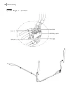
Страница 134: ...126 Troubleshooting Figure 8 6 Tailgate locking mechanism...
Страница 156: ...148 Multiplexing...
Страница 162: ...154 Multiplexing...
Страница 164: ...156 Lifting Arm Figure 10 1 Mounting bolts Figure 10 2 Helping Hand gripper Figure 10 3 Hoses...


