270
7.8 CR stitching cassette exposure
2
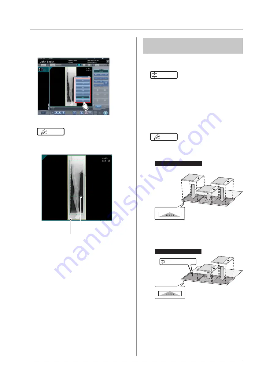
Press [OFF] or the button of the output
size to be changed on the Split Output
Size dialog box.
• The output size is changed .
HINT
•••••••••••••••••••••••••••••••••••••
• When output of split images is enabled, a frame ap-
pears on the image to indicate the area of the split im-
age that will be output .
Split output frame
Trimming frame
• The size of the trimming frame changes in accordance
with changes to the size of the image frame so that
images are automatically split into the selected section
size. Images can be split into a maximum of 3 sec
-
tions .
• If the split image is smaller than the trimming region,
the entire combined image may not completely fit
within the selected region .
•
If the configuration of the split images results in one
image, the split processing is not applied, and the split
output frame does not appear .
•••••••••••••••••••••••••••••••••••••••••••••••••••••
7 .8 .2 Exposure
The exposure method for CR stitching cassette is as
follows .
IMPORTANT
•••••••••••••••••••••••••••••••••••••
•
For the stitching exposure images, make sure that the
combined parts are combined in the correct positions .
• If there is gap between the combined images, manu-
ally adjust the image position of the combined parts
using the viewer screen (for stitching combination
position adjustment) . It is also recommended that you
arrange a measure in the combined image part during
exposure to confirm the combined parts easier.
•••••••••••••••••••••••••••••••••••••••••••••••••••••
HINT
•••••••••••••••••••••••••••••••••••••
• The sequence by which the CR cassette is mounted
on the CR stitching cassette is as follows (The UPPER
label indicates the top) .
(1)
Upper
Middle
Lower
UPPER label
(3)
(2)
If exposing with 3 REGIUS plates
•
To expose by mounting 2 CR cassettes on stitching
dedicated cassettes for 3 images, use the middle and
lower mounting positions only to mount the CR cas-
sette (the UPPER label indicated the top) .
If exposing with 2 REGIUS plates
(1)
UPPER label
(2)
Do not use the upper level.
Upper
Middle
Lower
•••••••••••••••••••••••••••••••••••••••••••••••••••••
Содержание CS-7
Страница 1: ...0197 Operation Manual EN 15 DIRECT DIGITIZER Version 1 30 ...
Страница 2: ......
Страница 8: ...8 ...
Страница 9: ...9 Introduction ...
Страница 18: ...18 ...
Страница 30: ...30 ...
Страница 31: ...31 Chapter 2 Product Overview This chapter describes the overview of this device ...
Страница 34: ...34 ...
Страница 74: ...74 ...
Страница 75: ...75 Chapter 4 General Operations This chapter describes general operation methods of this device ...
Страница 84: ...84 ...
Страница 120: ...120 ...
Страница 121: ...121 Chapter 6 Functions of each screen This chapter describes the functions of each screen of this device ...
Страница 197: ...197 Chapter 7 Various Functions This chapter describes the functions of this device ...
Страница 282: ...282 7 9 SIGMA stitching exposure 2 Press Return when image adjustment is completed The exposure screen is displayed ...
Страница 353: ...353 Chapter 8 Displayed Messages This chapter describes the displayed messages and the countermeasures ...
Страница 375: ...375 Chapter 9 Troubleshooting This chapter describes the countermeasures when the problems occur ...
Страница 383: ...383 Chapter 10 Error Codes This chapter describes the error codes and countermeasures ...
Страница 413: ...413 Chapter 11 Maintenance This chapter describes the items that require periodic maintenance ...
Страница 416: ...416 ...
Страница 417: ...417 Chapter 12 Specifications This chapter describes the specifications of this device ...
Страница 422: ...422 ...
Страница 423: ......
Страница 424: ...A47FBA01EN15 2017 01 12 JD ...


