TP-6255 7/06
31
Section 4 Fuel System
4.2.1
Bleeding the Fuel System
Bleed air from the fuel system to prevent starting failures
and/or erratic operation. One or more of the following
causes air to collect in the fuel system:
D
Operating the generator set until the fuel supply is
emptied.
D
Developing air leaks in the suction side of the fuel
system.
D
Replacing the fuel filter.
Note:
Connect the battery during the priming procedure
to allow engine cranking.
Note:
If the ADC 2100 indicates an overcrank fault
during this procedure, disconnect the negative
wire from the fuel solenoid (allowing the fuel
injection pump to fill with fuel) and repeat this
procedure after allowing the starter motor to cool
down.
Note:
Have a rag handy during the bleeding procedure.
Wipe up all spilled diesel fuel after bleeding the
system. Wash hands after any contact with fuel oil.
Procedure to Bleed the Fuel System
8/9EOZD and 6.5/7EFOZD Models and
13--32EOZD and 11--27EFOZD Models with Specs:
GM33035-GA1/GA2, GM33036-GA1/GA2, and
GM33037-GA1/GA2
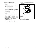
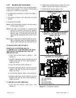
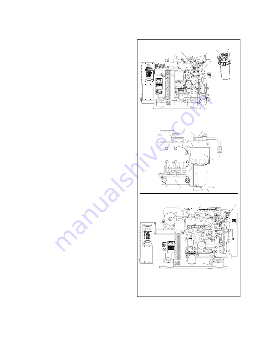
1. Loosen the fuel filter screw at position 1.
See
Figure 4-4.
2. Initiate the auto/start sequence until fuel, free of air
bubbles, flows from the vent screw at position 1.
Tighten the screw.
3. Loosen the fuel filter screw at position 2.
4. Initiate the auto/start sequence until fuel, free of air
bubbles, flows from the vent screw at position 2.
Tighten the screw.
5. Loosen the fuel injection pump screw at position 5.
6. Initiate the auto/start sequence until fuel, free of air
bubbles, flows from the vent screw at position 5.
Tighten the screw.
10--32EOZD and 9--27EFOZD Models
1. Loosen the fuel injection pump screw.
See
Figure 4-4.
2. Initiate the auto/start sequence until fuel, free of air
bubbles, flows from the injection pump screw.
3. Tighten the fuel injection pump screw.
1
2
3
4
5
TP-5592-3
1
2
5
4
3
ADV6843a-a
13--32EOZD & 11--27EFOZD Models with Specs:
GM33035-GA1/GA2, GM33036-GA1/GA2, &
GM33037-GA1/GA2
8/9EOZD and 6.5/7EFOZD
Models
1. Vent screw, position 1
2. Vent screw, position 2
3. Fuel filter
4. Fuel injection pump
5. Vent screw, position 5
6. Fuel injection pump screw
10--32EOZD and 9--27EFOZD Models
6
3
Figure 4-4
Fuel System (Typical)
Содержание 6.5-27EFOZD
Страница 1: ...Marine Generator Sets Models 8 32EOZD 6 5 27EFOZD TP 6255 7 06a Service ...
Страница 12: ...TP 6255 7 06 12 Service Assistance Notes ...
Страница 22: ...TP 6255 7 06 22 Section 1 Specifications Notes ...
Страница 28: ...TP 6255 7 06 28 Section 3 Intake and Exhaust System Notes ...
Страница 62: ...TP 6255 7 06 62 Section 7 Controller Notes ...
Страница 78: ...TP 6255 7 06 78 Section 8 Component Testing and Adjustment Notes ...
Страница 87: ...TP 6255 7 06 87 Section 10 Wiring Diagrams GM46351 Figure 10 2 Wiring Diagram for 9EOZD 7EFOZD Model ...
Страница 88: ...TP 6255 7 06 88 Section 10 Wiring Diagrams ADV6845A F Figure 10 3 Wiring Schematic for All Models ...
Страница 89: ...TP 6255 7 06 89 Section 10 Wiring Diagrams ADV6845B F Figure 10 4 Wiring Diagram Schematic for All Models ...
Страница 92: ...TP 6255 7 06 92 Section 10 Wiring Diagrams Notes ...
Страница 100: ...TP 6255 7 06 100 ...
Страница 101: ...TP 6255 7 06 101 ...
Страница 102: ...TP 6255 7 06 102 ...
Страница 103: ...TP 6255 7 06 103 ...

