background image

TP-6255 7/06

63

Section 8 Component Testing and Adjustment

Section 8 Component Testing and Adjustment

8.1 Theory of Operation

These generator sets utilize a rotating-field alternator to
produce AC voltage. Upon activation of the generator
master switch, DC current from the battery magnetizes
the rotor (field). When the magnetized rotor rotates
within the stator windings, an electrical voltage develops
within the stator. As engine speed and generator output
increase, the SCR module feeds rectified stator output
current to the rotor through the exciter to increase the
strength of the rotor field. As the rotor field increases in
strength, generator output also increases.

The

ADC 2100 monitors the generator output voltage
through leads 11 and 44 (for 1-phase models) or leads
V7, V8, and V9 (for 3-phase models) and adjusts the DC
current from the SCR module to the rotor to meet load
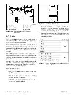
requirements. See Figure 8-1.

8.2 Separate Excitation

To determine the cause of no- or low-AC output, refer to
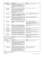
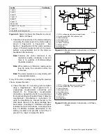
the troubleshooting flowchart in Figure 8-2.

Before

beginning the test procedures, read all of the safety
precautions at the beginning of this manual. Many of the
test procedures include additional safety precautions.

Check the condition of the alternator fuse before
performing the separate excitation procedure.

The

inline fuse is located in lead 55 of the wiring harness.
See Figure 8-1. If the fuse is not blown, use the following
procedure to separately excite the generator using an
external voltage source (a 12-volt automotive battery).

Separately exciting the generator can identify faulty
voltage regulation by the ADC 2100 or reveal a running
fault in the rotor and/or stator. An external power source
duplicates the role of the voltage regulator and excites
the generator field (rotor). A generator component that
appears to be in good condition while stationary may
exhibit a running open or short circuit while moving.
Short circuits can be caused by centrifugal forces acting
on the windings during rotation or insulation breakdown
as temperatures increase.

FP

11

3

4

55

2

1

44

7

5

2

8

6

1. Fuse
2. Power lead (55)
3. Excitation to rotor
4. Exciter

5. Rectifier module
6. Main field (rotor)
7. Stator windings
8. Sensing leads (11--44)

66

11

1

ADC

2100

SCR

4

(--)

(+)

AC1
AC2

G1
G2

44

66

66

55

55

G

F+

FN

FP

FN

3

AC

F +

F --

AC
AC

Figure 8-1

Generator Schematic
(Single-Phase Model Shown)

No Generator Output

Separate Excitation

Output within

Specifications

Check Rotor

Check Wiring, Fuses,

SCR Module and

ADC 2100

Check Stator

TP563273

Erratic or No Output

Figure 8-2

General Troubleshooting

Содержание 6.5-27EFOZD

Страница 1: ...Marine Generator Sets Models 8 32EOZD 6 5 27EFOZD TP 6255 7 06a Service ...

Страница 2: ...lable for future reference Record field installed kit numbers after installing the kits Generator Set Identification Numbers Record the product identification numbers from the generator set nameplate s Model Designation Specification Number Serial Number Accessory Number Accessory Description Engine Identification Record the product identification information from the engine nameplate Manufacturer...

Страница 3: ... 29 4 2 1 Bleeding the Fuel System 31 4 3 Fuel Pump 32 4 4 Governor 32 Section 5 Cooling System 33 5 1 General 33 5 2 Water Cooled Exhaust Manifold 34 5 3 Closed Heat Exchanger 34 5 4 Check and Fill Coolant 34 5 5 Flush and Clean Cooling System 35 5 6 Pressure Cap 35 5 7 Impeller Inspection and Replacement 35 5 8 Belt Tension 36 5 8 1 Seawater Pump Belt Tensioning Procedure 36 5 8 2 Battery Chargi...

Страница 4: ...Rectifier Module 67 8 6 Rotor 67 8 7 Stator 68 8 8 Voltage 70 8 8 1 Voltage Regulation 70 8 8 2 Voltage Adjustment 70 8 9 Four Lead Reconnection 72 8 9 1 100 120 Volt Configurations 72 8 9 2 100 120 200 240 Volt Configurations 72 8 9 3 200 240 Volt Configurations 73 8 10 Twelve Lead Reconnection 73 8 11 Fault Shutdown Tests 74 8 11 1 Controller Fault Shutdown Functions 74 8 11 2 Fault Shutdown Swi...

Страница 5: ... to prevent starting of the generator set by an automatic transfer switch remote start stop switch or engine start command from a remote computer Battery Sulfuric acid in batteries Can cause severe injury or death Wear protective goggles and clothing Battery acid may cause blindness and burn skin WARNING Battery electrolyte is a diluted sulfuric acid Batteryacid cancause severe injury or death Bat...

Страница 6: ... chemical burns nausea fainting or death Most chemicals such as used engine oil antifreeze coolant rustproofing agent inhibiting oil degreasing agent spraypaint andadhesivesare hazardoustohealth Readandfollow the user information found on the packaging Avoid inhalation and skin contact Use only in well ventilated areas and use a protective mask when spraying Store engine fluids and chemical produc...

Страница 7: ...xhaust system inspection test the carbon monoxide detector per the manufacturer s instructions and keep the detector operational at all times Operating the generator set Carbon monoxide can cause severenausea fainting or death Carbon monoxide is an odorless colorless tasteless nonirritating gas that can cause death if inhaled for even a short time Use the following precautions when installing ando...

Страница 8: ...nd gaseous fueled environment The electrical devices listed above are not ignition protected and are not certified to operate in a gasoline and gaseous fueled environmentsuchasanengineroomor near fuel tanks Acceptable locations are the wheelhouse and other living areas sheltered from rain and water splash Hazardous Noise Hazardous noise Can cause hearing loss Never operate the generator set withou...

Страница 9: ...oosen the pressure cap to relieve pressure WARNING Hot engine and exhaust system Can cause severe injury or death Do not work on the generator set until it cools WARNING Hot engine oil Can cause severe injury or death Avoid skin contact with hot oil Do not start or operate the generator set with the engine oil filler cap removed as hot oil can spray out Ensure that the lubrication system is not un...

Страница 10: ... a notice to the generator set after reconnecting the set to a voltage different from the voltage on the nameplate Order voltage reconnection decal 246242 from an authorized service distributor dealer NOTICE Hardware damage The engine and generator set may use both American Standard and metric hardware Use the correct size tools to prevent rounding of the bolt heads and nuts NOTICE When replacing ...

Страница 11: ...ce x in 001 003 Service Assistance For professional advice on generator power requirements and conscientious service please contact your nearest Kohler distributor or dealer D Consult the Yellow Pages under the heading Generators Electric D Visit the Kohler Power Systems website at KohlerPowerSystems com D Look at the labels and stickers on your Kohler product or review the appropriate literature ...

Страница 12: ...TP 6255 7 06 12 Service Assistance Notes ...

Страница 13: ...ne with a heat exchanger The 20EOZD 17EFOZD and 20EOZD 17 5EFOZD models are powered by a four cylinder water cooled four cycle diesel engine with a heat exchanger The 23EOZD 20EFOZD and 24EOZD 20EFOZD models are powered by a four cylinder water cooled four cycle turbocharged diesel engine with a heat exchanger The 28EOZD 23EFOZD and 32EOZD 27EFOZD models are powered by a four cylinder water cooled...

Страница 14: ...ed RPM 60 50 Hz 14 0 11 6 14 74 12 43 18 4 15 1 22 6 18 6 26 1 21 8 RPM 60 50 Hz 1800 1500 Lubrication system Pressure trochoid pump Lube oil capacity w filter L U S qts 2 3 2 4 3 6 3 8 4 7 5 0 Oil recommendation API CD or CF class Fuel recommendation API Diesel ISO 8217 DMA BS 2869 A1 or A2 Cetane No 45 min Fuel shutoff solenoid Electric Fuel pump Electric rotary vane Fuel pump priming Electric M...

Страница 15: ...eld 76 3 with sound shield 76 3 without sound shield Fuel inlet size 3 8 NPT with sound shield 1 4 NPT without sound shield Fuel return size 3 8 NPT with sound shield 1 4 NPT without sound shield Fuel injection pressure kgf cm sq psi 120 1706 120 130 1706 1849 200 210 2844 2986 Intake exhaust valve clearance cold mm in 0 15 0 25 0 006 0 0010 Fuel pump static pressure psi 4 8 12 volt pump or 5 5 9 ...

Страница 16: ...ation system Pressure trochoid pump Lube oil capacity w filter L U S qts 5 8 6 1 10 2 10 78 Oil recommendation API CD or CF class Fuel recommendation API Diesel ISO 8217 DMA BS 2869 A1 or A2 Cetane No 45 min Fuel shutoff solenoid Electric Fuel pump Electric rotary vane Fuel pump priming Electric Max recommended fuel pump lift m ft 1 2 4 Battery voltage 12 volts standard 24 volts optional Battery c...

Страница 17: ... inlet size 3 8 NPT with sound shield 1 4 NPT without sound shield Fuel return size 3 8 NPT with sound shield 1 4 NPT without sound shield Fuel injection pressure kgf cm sq psi 200 210 2844 2986 220 230 3129 3271 Intake exhaust valve clearance cold mm in 0 15 0 25 0 006 0 0010 Fuel pump static pressure psi 4 8 12 volt pump or 5 5 9 24 volt pump Pressure cap rating kPa psi 97 14 ...

Страница 18: ...5 135 135 135 135 55 66 volts 180 180 180 180 180 Cold stator resistance 1 2 3 4 ohms 0 26 0 26 0 19 0 12 0 12 55 66 ohms 2 11 2 11 1 89 1 46 1 46 Component Specification 20EOZD 17EFOZD 23EOZD 20EFOZD 28EOZD 23EFOZD 32EOZD 27EFOZD Hot exciter field voltage amperage readings at rated voltage No load 63 Hz volts amps 6 1 0 6 1 0 18 0 7 18 0 7 Full load 60 Hz volts amps 14 2 1 16 2 4 42 1 6 45 1 7 Ex...

Страница 19: ...4 2 5 3 6 7 10 8 11 9 12 volts 150 145 140 140 55 66 volts 170 165 158 158 Cold stator resistance 1 4 2 5 3 6 7 10 8 11 9 12 ohms 0 09 0 06 0 04 0 04 55 66 ohms 2 5 1 5 1 3 1 3 Component Specification 28EOZD 23EFOZD 32EOZD 27EFOZD Hot exciter field voltage amperage readings at rated voltage No load 63 Hz volts amps 21 0 8 21 0 8 Full load 60 Hz volts amps 64 2 3 70 2 5 Exciter field resistance col...

Страница 20: ...he load lead cable 20 Cooling air inlet 21 AC circuit breaker coverplate 22 Anticorrosion zinc anode seawater drain all models except 13 24EOZD 11 20EFOZD models 23 Belt guard 24 V belts 25 Coolant freshwater drain all models except 13 24EOZD 11 20EFOZD models 26 Heat exchanger all models except 13 24EOZD 11 20EFOZD models 27 Heat exchanger 13 24EOZD 11 20EFOZD models 28 Seawater drain 13 24EOZD 1...

Страница 21: ...m 28 ft lbs Flex disc to flywheel 19 Nm 14 ft lbs Flywheel bolts 78 5 88 3 Nm 58 65 ft lbs 83 3 88 2 Nm 62 65 ft lbs SCR to end bracket 4 Nm 35 in lbs Generator Model 20EOZD 17EFOZD 17 5EFOZD 1 and 3 Ph 23EOZD 20EFOZD 24EOZD 20EFOZD 28EOZD 23EFOZD 1 and 3 Ph 32EOZD 27EFOZD 1 and 3 Ph Overbolts 34 Nm 25 ft lbs Rotating diode board 38 Nm 28 ft lbs Back plate to engine block 36 6 Nm 27 ft lbs Rotor h...

Страница 22: ...TP 6255 7 06 22 Section 1 Specifications Notes ...

Страница 23: ... Before working on the generator set or connected equipment disable the generator set as follows 1 Move the generator set master switch to the OFFposition 2 Disconnectthepowertothebatterycharger 3 Remove the battery cables negative lead first Reconnect the negative lead last when reconnecting the battery Follow these precautions to prevent starting of the generator set by an automatic transfer swi...

Страница 24: ... shorter engine life Figure 2 1 show the recommended Society of Automotive Engineers SAE viscosity designation for given operating temperature ranges C F 30 20 10 0 10 20 30 40 0 20 40 60 80 100 C F 10W 20W 10W30 20 30 40 TP 5856 1 SAE Service Grade Operating Temperature 15W40 Figure 2 1 Engine Oil Selection Note Failure to observe the oil specifications may cause inadequate lubrication oil pressu...

Страница 25: ...ure 3 1 Air Cleaner Element Element 14 15 5 23 24EOZD and 11 5 13 20EFOZD Models These models use a round polyurethane sound absorbing type intake silencer to silence the intake air drawn into the cylinder head from the intake port Besides providing a silencing effect the silencer also acts as an air cleaner Clean the silencer more frequently if operating in dirty dusty conditions See Figure 3 2 a...

Страница 26: ...tal parts and replace them as needed D Check for loose corroded or missing clamps Tighten or replace the hose clamps and or hangers as needed D Check that the exhaust outlet is unobstructed D Visually inspect the exhaust system for exhaust leaks blowby Check for carbon or soot residue on exhaust components Carbon and soot residue indicates an exhaust leak Seal leaks as needed 3 3 Servicing Mixing ...

Страница 27: ...or assembly turbo 3 Housing assembly blower 4 Plate assembly seal 5 Circlips 6 Housing assembly bearing 7 Heat protector Figure 3 3 Turbocharger Inspection 1 2 3 4 5 TP 6071 32 1 Turbocharger assembly 2 Gaskets 3 Exhaust elbow 4 Exhaust manifold 5 Petcock PT 1 8 Figure 3 4 Turbocharger Components Typical ...

Страница 28: ...TP 6255 7 06 28 Section 3 Intake and Exhaust System Notes ...

Страница 29: ...d Under normal conditions replace the fuel filter element at the specified interval in the generator set s operation manual Use the following procedure to replace the fuel filter Fuel Filter Replacement Procedure 8 9EOZD and 6 5 7EFOZD Models 1 Place the generator set on off switch in the OFF position 2 Disconnect the generator set engine starting battery negative lead first 3 Close the fuel suppl...

Страница 30: ...nner 5 Clean the contact surface of the fuel oil filter adapter 6 Lightly lubricate the gasket surface of the new fuel filter with fresh fuel oil Thread the filter on the adapter until the gasket makes contact hand tighten the filter an additional one half turn Wash hands after any contact with fuel oil 7 Open the fuel supply valve 8 Reconnect the generator set engine starting battery negative lea...

Страница 31: ... GM33035 GA1 GA2 GM33036 GA1 GA2 and GM33037 GA1 GA2 1 Loosen the fuel filter screw at position 1 See Figure 4 4 2 Initiate the auto start sequence until fuel free of air bubbles flows from the vent screw at position 1 Tighten the screw 3 Loosen the fuel filter screw at position 2 4 Initiate the auto start sequence until fuel free of air bubbles flows from the vent screw at position 2 Tighten the ...

Страница 32: ...djusting the amount of fuel supplied to the engine according to changes in the load The governor requires no regular service The factory adjusts the governor during run in and further adjustment should not be needed unless greatly varying load conditions are encountered or if poor governor control develops after extended usage 60 Hz generator sets are designed to operate in the range of 57 63 Hz 1...

Страница 33: ...e pressure from the cooling system before removing the pressure cap To releasepressure coverthepressure capwith athick clothand then slowly turn the cap counterclockwise to the first stop Remove the cap after pressure has been completely released and the engine has cooled Check the coolant level at the tank if the generator set has a coolant recovery tank NOTICE Saltwater damage Saltwater quickly ...

Страница 34: ...anol antifreeze or mix them with the specified coolant Consult the engine manufacturer s operation manual for engine coolant specifications 5 4 Check and Fill Coolant Note Do not add coolant to a hot engine Adding coolant to a hot engine can cause the cylinder block or cylinder head to crack Wait until the engine has cooled Maintain the coolant level in the coolant recovery tank at approximately 1...

Страница 35: ...ed on the cap body 5 7 Impeller Inspection and Replacement The belt driven seawater pump is located on the service side of the generator set Check and change the seawater pump impeller at the interval specified in the service schedule Follow the instructions included with the impeller kit If the instructions are not included with the kit use the following procedure Impeller Inspection and Replacem...

Страница 36: ...ecifications adjust as necessary using the following procedures 1 11 10 9 8 7 6 5 2 3 4 TP 5586 3 1 Engine driven water pump pulley 2 Adjusting arm pivot screw 3 Battery charging alternator pulley 4 Alternator adjusting screw 5 Alternator pivot screw 6 Check the alternator belt tension here 7 Crankshaft pulley 8 Check the seawater pump belt tension here 9 Seawater pump adjusting screw 10 Seawater ...

Страница 37: ... Zinc Anode Replacement 1 With the generator set cooled close the seacock open the petcock on the engine and drain the coolant into a suitable container 2 Remove the anticorrosion zinc anode plug from the heat exchanger 3 Use a wire brush to remove the loose corrosion on the anticorrosion zinc anode Replace the anode according to Figure 5 7 and Figure 5 8 Anticorrosion Zinc Anode Replacement Model...

Страница 38: ...d finger tighten only Do not overtighten Waterline 1 2 3 7 8 9 17 10 11 12 13 14 15 16 20 18 6 5 4 TP 5586 3 19 1 Mounting base 2 Retaining cap 3 Reed valve assembly 4 Silencer vertical lift 1 2 m 4 ft max 5 Exhaust mixer elbow distance above waterline if less than 23 cm 9 in siphon break is required 6 Siphon break distance above waterline 30 5 cm 1 ft min 7 Siphon break 8 Exhaust mixer elbow 9 He...

Страница 39: ...ler s application program and for more information on updating the application program 6 3 General Before beginning the troubleshooting procedures read all the safety precautions at the beginning of this manual Hazardous voltage Can cause severe injury or death Operate the generator set only when all guards and electrical enclosures are in place Moving rotor WARNING Grounding electrical equipment ...

Страница 40: ...e Section 10 If the fuse continues to blow and the previous step did not identify the cause remove the leads from the P14 connector using a pin pusher part 241918 large or 241919 small If replacing the leads does not solve the problem replace the RIB Section 7 10 Section 10 Crank relay on relay interface board RIB Check connections to the RIB Check for 12VDC to the RIB between PF2 and 71N Check fo...

Страница 41: ... stops suddenly Fault shutdown Check for a fault shutdown code on the Advanced Digital Control s LED display Correct the fault and then move the generator set master switch to the OFF RESET position to reset the ADC Section 7 4 No fuel Check the fuel supply Fuel line restriction Inspect fuel lines Air cleaner clogged Replace element Section 3 Blown controller fuse F3 Replace fuse Section 8 12 Blow...

Страница 42: ...ate cooling Inspect cooling system for obstructions Air cleaner clogged Replace element Section 3 Low output or i Generator overloaded Reduce load Generator Set I M p excessive drop in voltage Incorrect controller configuration Check and adjust the controller configuration parameters Section 7 5 voltage Incorrect controller voltage settings Check and adjust the controller voltage settings Section ...

Страница 43: ...age Section 7 7 Controller Check fuses wiring and connections Before replacing the controller replace the SCR module and test voltage Section 7 5 Section 7 7 Section 7 11 No output voltage AC output circuit breaker open Check for AC voltage on the generator side of the circuit breaker If there is AC voltage on the generator side of the breaker then a problem in the load circuits is causing the lin...

Страница 44: ...his table See Generator set operates erratically this table Broken or damaged vibromount s Check and replace as necessary Loose or vibrating sheet metal housing Retighten screws replace rivets Exhaust piping or air inlets outlets not securely installed Inspect for loose parts and secure if necessary Excessive engine generator vibration Check rotor crankshaft bearing etc disassembly of engine and o...

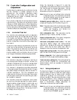
Страница 45: ...tion and faults are described in Section 7 4 Controller configuration and adjustment are covered in Section 7 5 A silicon controlled rectifier SCR module works with the controller to regulate the output voltage See Section 7 7 A relay interface board RIB is used with the ADC controller Section 7 10 describes the standard and optional RIBs 1 GM29253 1 Junction box louvered panel 2 SCR module 3 Rela...

Страница 46: ...tton use for setup and adjustment only 3 Upanddownarrowbuttons useforsetupandadjustmentonly 4 Generator set master switch GM28707A C Figure 7 2 Advanced Digital Control Controller Display Item Description Crank indication Displays CC_1 CC_2 or CC_3 to indicate the 1st 2nd or 3rd attempt to start the engine The last digit flashes during the crank cycle rest periods Runtime hours Displays total gene...

Страница 47: ...es three crank cycles 15 seconds crank and 15 seconds off If the generator set does not start in three attempts the system shuts down on an overcrank fault When the engine comes up to speed the low oil pressure switch contacts open Note The controller circuit board prevents fault shutdowns during startup until the crank disconnect relay energizes The cyclic cranking cycle is programmed into the AD...

Страница 48: ... controller will not power down if the master switch is in the AUTO position If the ADC 2100 is not configured for a CAN gauge the controller will power down after 48 hours if the master switch is in the AUTO position If the generator has been started the controller will power down 48 hours after the generator stops 7 4 Faults 7 4 1 Fault Shutdowns Under the fault conditions listed in Figure 7 4 t...

Страница 49: ...ve 10 seconds after engine start 10 second inhibit Contact an authorized distributor dealer for service if problem continues OS Overspeed shutdown Shutdown occurs if the engine speed exceeds 115 of the normal running speed for more than 0 3 seconds Contact an authorized distributor dealer for service if problem continues OU Overvoltage shutdown Shutdown occurs if the voltage exceeds 120 of the vol...

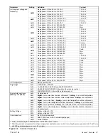
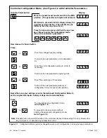
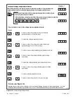
Страница 50: ...roller communications setting for optional meters Check these settings after controller replacement and change them if necessary to match the settings shown in Figure 7 6 Follow the instructions in Figure 7 7 to enter the configuration mode while the engine is not running and then step through the following parameters Use the up and down arrow buttons to select the appropriate setting for the appl...

Страница 51: ...hase 4 Wire 50 Hz 120 208 VAC Wye Uu19 Three phase 4 Wire 60 Hz 220 380 VAC Wye Uu20 Three phase 4 Wire 60 Hz 240 416 VAC Wye Uu20 Three phase 4 Wire 60 Hz 230 400 VAC Wye Uu21 Three phase 4 Wire 50 Hz 220 380 VAC Wye Uu22 Three phase 4 Wire 50 Hz 240 416 VAC Wye Unit configuration Uc00 Marine generator set Engine type Ec01 8 9EOZD 6 5 7EFOZD g yp Ec02 10 20EOZD 9 17 5EFOZD and 24EOZD 20EFOZD Ec07...

Страница 52: ...0 U u 0 x 1 0 4 0 A d n c Press Now release the Select button or To enter advanced configuration mode Go to Figure 7 8 or To proceed to the save mode without entering the advanced configuration mode Go to Figure 7 9 Now either save your settings or enter the Advanced Configuration Mode to set the engine data inputs battery voltage and communications Press S A V E E d 0 x E c 0 x Note Shaded boxes ...

Страница 53: ...ode engine data input types battery voltage and engine communications To save changes To discard changes without saving or Note Be sure to save your settings before exiting the configuration mode The controller reverts to the last saved settings when the master switch is moved to the OFF RESET position x in the runtime hours display above denotes any number from 0 to 9 S A V E Y E S Now move the m...

Страница 54: ...ode or To raise or lower the voltage stability gain in smaller increments To enter volts Hz adjustment mode To raise or lower the volts Hz 00 low 09 high or Hold Wait about 5 seconds until the display changes from runtime hours to the program version number Press the down arrow key and then the up arrow key 3 times to enter the adjustment mode This is the controller password x x x x x x 1 P 1 P 2 ...

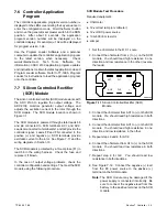
Страница 55: ...eads FP and FN connected to the positive and negative SCR terminals provide excitation current to the rotor See Figure 7 11 and the wiring diagrams in Section 10 The SCR module is protected by a 10 amp fuse F1 in lead 55 in the wiring harness Check the fuse and replace it if blown In the case of output voltage problems check the controller configuration and settings Then test the SCR module using ...

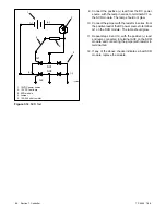
Страница 56: ...eries to terminal AC1 on the SCR module The lamp should not glow 10 Connect the jumper with the resistor in series from the positive lead of the DC power source to terminal G1 on the SCR module The lamp should glow 11 Repeat steps 9 and 10 with the positive lead and lamp connected to terminal AC2 on the SCR module and connecting the jumper with resistor to terminal G2 12 If any of the above checks...

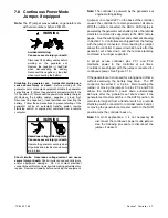
Страница 57: ...l jewelry before servicing the equipment Note The controller is powered by the generator set engine starting battery A jumper on connector P7 on the back of the controller causes the controller to remain powered at all times With the jumper connected the ADC s LED display is powered by the generator set s battery Also the remote start stop command is supported via the ADC remote gauge See the wiri...

Страница 58: ... the controller s back cover See Figure 7 13 4 Locate the P7 connector near the top of the controller See Figure 7 13 Remove the jumper from pins 1 and 2 of the P7 connector If the P7 connector has three pins connect the jumper across pins 2 and 3 for storage 5 Replace the controller s back cover and secure the cover screws 6 Reconnect the three pink connectors to the generator set master switch 7...

Страница 59: ...r leads FP and FN 2 Pull the board straight off the mounting stand offs 3 Snap the new board onto the stand offs and reconnect P14 and the exciter leads The generator set may be equipped with an optional RIB which contains the K4 auxiliary run relay and K1 common fault relay in addition to the standard relays The optional relay board kit includes a wiring harness for connection of customer equipme...

Страница 60: ...on 8 8 2 and the governor adjustment instructions in Section 4 4 ADC 2100 Controller Replacement Procedure 1 Place the generator set master switch in the OFF position 2 Disconnect power to the battery charger if equipped 3 Disconnect the generator set engine starting battery negative lead first Accidental starting Can cause severe injury or death Disconnect the battery cables before working on the...

Страница 61: ...tive lead last 15 Reconnect power to the battery charger if equipped 16 Follow the instructions in Section 7 5 2 to change the new controller s configuration settings to match the generator set system voltage and frequency unit configuration engine type engine data input types battery voltage and communications settings 17 Use a voltmeter to check the output voltage Follow the instructions in Sect...

Страница 62: ...TP 6255 7 06 62 Section 7 Controller Notes ...

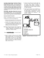
Страница 63: ...itional safety precautions Check the condition of the alternator fuse before performing the separate excitation procedure The inline fuse is located in lead 55 of the wiring harness See Figure 8 1 If the fuse is not blown use the following procedure to separately excite the generator using an external voltage source a 12 volt automotive battery Separately exciting the generator can identify faulty...

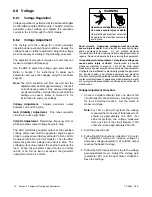
Страница 64: ...e FN exciter leads as shown in Figure 8 3 Note and record the ammeter reading Note The approximate ammeter reading should be the battery voltage divided by the specified rotor resistance See Section 1 Specifications for the specified rotor resistance values Example 12 volts battery voltage 3 5 ohms rotor resistance 3 4 amps rotor current 3 Start the engine and check that the ammeter reading remain...

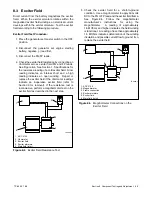
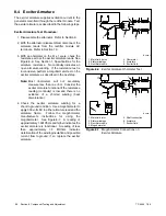
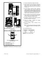
Страница 65: ...ter field if the ohmmeter readings indicate an inoperative exciter field refer to Section 9 for removal If the resistance test is inconclusive perform a megohmmeter test on the exciter field as described in the next step 1 3 4 FN FP TP 5983 7 2 1 ADC 2100 2 Ohmmeter 3 Exciter field 4 Exciter armature 5 Main field rotor 5 Figure 8 4 Exciter Field Resistance Test 5 Check the exciter field for a shor...

Страница 66: ...one ohm Consider the exciter armature functional if the resistance reading continuity is low and there is no evidence of a shorted winding heat discoloration 4 Check the exciter armature winding for a short to ground condition Use a megohmmeter to apply 500 volts DC to either armature lead and the armature frame Follow the megohmmeter manufacturer s instructions for using the megohmmeter See Figur...

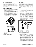
Страница 67: ...e generator prior to performing this test See Section 9 Generator Main Field Rotor Test Procedure 1 With the generator disassembled disconnect the generator main field windings at the rectifier module terminals F and F 2 Check the main field resistance by connecting an ohmmeter across the main field F and F leads See Figure 8 9 See Section 1 Specifications for the resistance reading A low reading ...

Страница 68: ...Leads 55 and 66 are the voltage regulator supply and sensing leads Refer to the schematic in Figure 8 11 when performing the following tests Stator Test Procedure 1 Place the generator master switch in the OFF position 2 Disconnect the generator set engine starting battery negative lead first 3 Check the generator output lead connections See Section 10 Wiring Diagrams 3 4 55 2 1 44 11 6196 66 Figu...

Страница 69: ...ground condition using a megohmmeter See Figure 8 14 for a single phase megohmmeter connections and Figure 8 15 for three phase megohmmeter connections Apply 500 volts DC to any stator lead from each winding and the stator frame Follow the megohmmeter manufacturer s instructions for using the megohmmeter Repeat the test on the other leads until all of the stator windings have been tested A reading...

Страница 70: ...al 60 Hz or 50 Hz as load is accepted the generator output also returns to normal Hazardous voltage Can cause severe injury or death Operate the generator set only when all guards and electrical enclosures are in place Moving rotor WARNING Short circuits Hazardous voltage current can cause severe injury or death Short circuits can cause bodily injury and or equipment damage Do not contact electric...

Страница 71: ...ernor as described in Section 4 4 7 Set the voltmeter to measure voltage Adjust the volts Hz parameter 3P until the voltage level measured by the voltmeter begins to drop When set the generator as load is applied attempts to maintain normal output until the engine speed drops below the cut in frequency set in step 6 8 Set the voltmeter to measure frequency Adjust the engine speed to the operating ...

Страница 72: ... 3 2 1 L0 Neutral L0 Ground Load Side Line Side Two Pole Circuit Breaker Jumper lead Figure 8 18 100 120 Volt 3 Wire Configuration 8 9 2 100 120 200 240 Volt Configurations The 100 120 200 240 volt configuration does not use a jumper lead If the unit was originally wired for straight 100 120 volt 3 wire remove the jumper lead see Figure 8 18 for location Select a two pole circuit breaker Applicati...

Страница 73: ...all cases follow the National Electrical Code NEC guidelines Reconnect the stator leads of the generator set to change output phase or voltage Refer to the following procedure and connection schematics Follow all safety precautions at the front of this manual and in the text during reconnection procedure NOTICE Voltagereconnection Affixanoticetothegeneratorsetafter reconnecting the set to a voltag...

Страница 74: ...er ED Hot engine and exhaust system Can cause severe injury or death Do not work on the generator set until it cools WARNING Servicing the exhaust system Hot parts can cause severe injury or death Do not touch hot engine parts The engine and exhaust system components become extremely hot during operation Open the generator set output circuit breaker before beginning the test See Figure 8 16 for th...

Страница 75: ...Set the generator set master switch to the OFF position and allow the generator set to cool Disconnect the CTS and use an ohmmeter to measure the resistance across the sensor The sensor resistance varies with temperature and should be within the values shown in Figure 8 24 If the resistance is very low indicated a short circuit or very high indicating an open circuit replace the CTS Low Oil Pressu...

Страница 76: ...hort circuits can cause bodily injury and or equipment damage Do not contact electrical connections with tools or jewelry while making adjustments or repairs Remove all jewelry before servicing the equipment To further check generator set components disconnect the battery and remove wiring harness plugs from the ADC circuit board Use an ohmmeter to check the continuity of the components listed in ...

Страница 77: ...tinuity check wiring P16 3 and P16 6 stator leads 55 and 66 R x 1 OFF RESET Zero ohms continuity If no continuity check fuse F1 and wiring Controller fuse and wiring P1 24 and battery positive R x 100 OFF RESET Zero ohms continuity If no continuity is found check fuse F3 and wiring Auxiliary winding fuse 10 amp fuse P16 3 and stator lead 55 R x 100 OFF RESET Zero ohms continuity If no continuity i...

Страница 78: ...TP 6255 7 06 78 Section 8 Component Testing and Adjustment Notes ...

Страница 79: ...he generator set engine starting battery negative lead first Accidental starting Can cause severe injury or death Disconnect the battery cables before working on the generator set Remove the negative lead first when disconnecting the battery Reconnect the negative lead last when reconnecting the battery WARNING Sound Shield Equipped Models For access to the generator set to perform regular mainten...

Страница 80: ...igure 9 2 ADC 2100 Mounting Screws 11 Remove the junction box louvered panel See Figure 9 3 and Figure 9 4 1 2 1 ADC 2100 2 Junction box louvered panel Figure 9 3 Covers 1 1 Junction box louvered panel 2 SCR module 3 Relay board 4 Engine harness to controller connection 5 Generator set master switch 6 ADC 2100 7 Line circuit breaker plate 8 Junction box 6 7 8 3 2 5 4 Figure 9 4 Advanced Digital Co...

Страница 81: ...shaft guiding the rotor leads through the armature bores See Figure 9 6 558865 1 2 3 4 1 Armature 2 Armature retaining bolt 3 Rotor leads 4 Rectifier board Figure 9 6 Armature Removal 18 Attach a hoist hook to the generator lifting eye See Figure 9 7 Note The hoist capacity rating should be one half ton or greater 19 Remove the two vibromount bolts See Figure 9 7 20 Raise the alternator end and pl...

Страница 82: ...sembly with a permanent marker 26 Remove the four screws with spacers and the four screws without spacers See Figure 9 9 27 Remove the fan and fan spacers See Figure 9 9 28 Remove the eight bolts and remove the drive disc rotor assembly from the engine flywheel See Figure 9 10 29 Clamp the rotor in a soft jaw vise Remove the eight bolts and remove the drive disc assembly from the rotor See Figure ...

Страница 83: ...r spacers washers and locknuts Note Install the fan with the flange side facing away from the flywheel 4 Replace the O ring in the end bracket bearing bore Use a sling to support the stator assembly while installing the stator over the rotor Do not damage the rotor See Figure 9 13 5588612 1 1 O ring Figure 9 13 Stator Installation 5 Install the four overbolts the two long bolts in the lower holes ...

Страница 84: ... Exciter Field 11 Install tie wraps to secure the wires as necessary 12 Reconnect the leads to the circuit breaker and neutral stud LO as marked during disassembly Note Check the generator set nameplate to verify the original voltage configuration 13 Reconnect the P1 P15 and P16 connectors Connect the ground strap using bolt washer and lock washer install the lock washer against the ground strap 1...

Страница 85: ...onnecting the battery Follow these precautions to prevent starting of the generator set by an automatic transfer switch remote start stop switch or engine start command from a remote computer Hazardous voltage Can cause severe injury or death Operate the generator set only when all guards and electrical enclosures are in place Moving rotor WARNING Grounding electrical equipment Hazardous voltage c...

Страница 86: ...TP 6255 7 06 86 Section 10 Wiring Diagrams GM30264 F Figure 10 1 Wiring Diagram for All Models Except 9EOZD 7EFOZD See Figure 10 2 for 9EOZD 7EFOZD Model ...

Страница 87: ...TP 6255 7 06 87 Section 10 Wiring Diagrams GM46351 Figure 10 2 Wiring Diagram for 9EOZD 7EFOZD Model ...

Страница 88: ...TP 6255 7 06 88 Section 10 Wiring Diagrams ADV6845A F Figure 10 3 Wiring Schematic for All Models ...

Страница 89: ...TP 6255 7 06 89 Section 10 Wiring Diagrams ADV6845B F Figure 10 4 Wiring Diagram Schematic for All Models ...

Страница 90: ...mler American Solenoid Early Rectangular Design Kraus Naimler American Solenoid Newer Round Design 2 1 3 4 6 5 7 8 1 2 6 5 3 4 8 7 L1 L2 To Generator Set To Shore Power To Load 3 2 4 1 7 6 8 5 L1 L2 To Generator Set To Shore Power To Load 3 Wire Generator Sets 2 1 3 4 6 5 7 8 L0 10 9 11 12 1 2 6 5 3 4 8 7 9 10 14 13 L1 L2 To Generator Set To Shore Power To Load 3 Wire Generator Sets L0 3 2 4 1 7 6...

Страница 91: ...s 10 2 Manual Marine Ship to Shore 4 Wire Transfer Switch 7 6 8 5 11 10 12 9 15 14 16 13 L2 L3 To Generator Set To Shore Power To Load 4 Wire three phase Generator Sets L0 3 2 4 1 L1 L2 L3 L0 L1 L2 L3 L0 L1 Kraus Naimer American Solenoid I 940 ...

Страница 92: ...TP 6255 7 06 92 Section 10 Wiring Diagrams Notes ...

Страница 93: ...oled cyl cylinder D A digital to analog DAC digital to analog converter dB decibel dBA decibel A weighted DC direct current DCR direct current resistance deg degree dept department dia diameter DI EO dual inlet end outlet DIN Deutsches Institut fur Normung e V also Deutsche Industrie Normenausschuss DIP dual inline package DPDT double pole double throw DPST double pole single throw DS disconnect s...

Страница 94: ...al OS oversize overspeed OSHA Occupational Safety and Health Administration OV overvoltage oz ounce p pp page pages PC personal computer PCB printed circuit board pF picofarad PF power factor ph phase PHC Phillips head crimptite screw PHH Phillips hex head screw PHM pan head machine screw PLC programmable logic control PMG permanent magnet generator pot potentiometer potential ppm parts per millio...

Страница 95: ...elow top of nut Figure 1 Acceptable Bolt Lengths Steps for common hardware application 1 Determine entry hole type round or slotted 2 Determine exit hole type fixed female thread weld nut round or slotted For round and slotted exit holes determine if hardware is greater than 1 2 inch in diameter or 1 2 inch in diameter or less Hardware that is greater than 1 2 inch in diameter takes a standard nut...

Страница 96: ... 27 7 16 14 ft lbs Nm 29 39 44 60 63 85 7 16 20 ft lbs Nm 32 43 50 68 70 95 1 2 13 ft lbs Nm 44 60 68 92 96 130 1 2 20 ft lbs Nm 49 66 76 103 108 146 9 16 12 ft lbs Nm 60 81 98 133 138 187 9 16 18 ft lbs Nm 67 91 109 148 154 209 5 8 11 ft lbs Nm 83 113 135 183 191 259 5 8 18 ft lbs Nm 94 128 153 208 216 293 3 4 10 ft lbs Nm 147 199 240 325 338 458 3 4 16 ft lbs Nm 164 222 268 363 378 513 1 8 ft lb...

Страница 97: ...nal External Tooth Lock Hardness Grades American Standard Grade 2 Grade 5 Grade 8 Grade 8 9 Hex Socket Head Metric Number stamped on hardware 5 8 shown 5 8 Allent head screw is a trademark of Holo Krome Co Phillipsr screw is a registered trademark of Phillips Screw Company Sample Dimensions 1 4 20 x 1 Major Thread Diameter In Fractional Inches Or Screw Number Size Length In Inches Screws and Bolts...

Страница 98: ... 6024 2 7 16 14 x 1 00 X 6024 8 7 16 14 x 1 25 X 6024 3 7 16 14 x 1 50 X 6024 4 7 16 14 x 2 00 X 6024 11 7 16 14 x 2 75 X 6024 12 7 16 14 x 6 50 X 129 15 1 2 13 x 75 X 129 17 1 2 13 x 1 00 X 129 18 1 2 13 x 1 25 X 129 19 1 2 13 x 1 50 X 129 20 1 2 13 x 1 75 X 129 21 1 2 13 x 2 00 X 129 22 1 2 13 x 2 25 X 129 23 1 2 13 x 2 50 X 129 24 1 2 13 x 2 75 X 129 25 1 2 13 x 3 00 X 129 27 1 2 13 x 3 50 X 12...

Страница 99: ...1 25 x 20 M933 10020 60 M10 1 50 x 20 M933 10025 60 M10 1 50 x 25 M933 10030 60 M10 1 50 x 30 M933 10030 82 M10 1 50 x 30 M961 10035 60 M10 1 25 x 35 M933 10035 60 M10 1 50 x 35 M933 12016 60 M12 1 75 x 16 M933 12020 60 M12 1 75 x 20 M933 12025 60 M12 1 75 x 25 M933 12025 82 M12 1 75 x 25 M933 12030 60 M12 1 75 x 30 M933 12040 60 M12 1 75 x 40 M933 12040 82 M12 1 75 x 40 M961 14025 60 M14 1 50 x 2...

Страница 100: ...TP 6255 7 06 100 ...

Страница 101: ...TP 6255 7 06 101 ...

Страница 102: ...TP 6255 7 06 102 ...

Страница 103: ...TP 6255 7 06 103 ...

Страница 104: ...hler Wisconsin 53044 Phone 920 565 3381 Fax 920 459 1646 For the nearest sales service outlet in the US and Canada phone 1 800 544 2444 KohlerPowerSystems com Kohler Power Systems Asia Pacific Headquarters 7 Jurong Pier Road Singapore 619159 Phone 65 6264 6422 Fax 65 6264 6455 ...

Отзывы: