

TP-6255 7/06
81
Section 9 Generator Disassembly/Reassembly
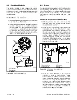
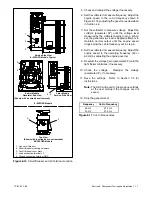
13. Disconnect the FP and FN leads.
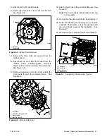
14. Remove the four bolts to remove the exciter field.
See Figure 9-5.
558864
1
2
1. Bolts (4)
2. Exciter field
Figure 9-5
Exciter Field Removal
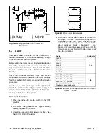
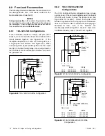
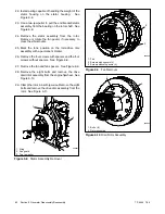
15. Remove the three bolts and spacers from the
rectifier board.
16. Disconnect the main field rotor leads from the
rectifier
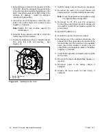
board
positive/negative
terminals.
Remove the armature retaining bolt and washer.
See Figure 9-6.
17. Remove the armature from the shaft, guiding the
rotor leads through the armature bores.
See
Figure 9-6.
558865
1
2
3
4
1. Armature
2. Armature retaining bolt
3. Rotor leads
4. Rectifier board
Figure 9-6
Armature Removal
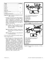
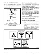
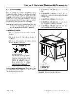
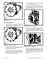
18. Attach a hoist hook to the generator lifting eye. See
Figure 9-7.
Note:
The hoist capacity rating should be one-half
ton or greater.
19. Remove the two vibromount bolts. See Figure 9-7.
20. Raise the alternator end and place a wood block
under the locator plate. Lower the alternator until
the wood block supports the backplate.
See
Figure 9-7.
21. Remove the four overbolts from the end bracket.
558866
1
3
2
4
1. Lifting eye
2. Backplate
3. Wood block
4. Vibromounts
Figure 9-7
Supporting the Generator, Typical
Содержание 6.5-27EFOZD
Страница 1: ...Marine Generator Sets Models 8 32EOZD 6 5 27EFOZD TP 6255 7 06a Service ...
Страница 12: ...TP 6255 7 06 12 Service Assistance Notes ...
Страница 22: ...TP 6255 7 06 22 Section 1 Specifications Notes ...
Страница 28: ...TP 6255 7 06 28 Section 3 Intake and Exhaust System Notes ...
Страница 62: ...TP 6255 7 06 62 Section 7 Controller Notes ...
Страница 78: ...TP 6255 7 06 78 Section 8 Component Testing and Adjustment Notes ...
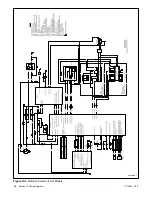
Страница 87: ...TP 6255 7 06 87 Section 10 Wiring Diagrams GM46351 Figure 10 2 Wiring Diagram for 9EOZD 7EFOZD Model ...
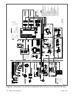
Страница 88: ...TP 6255 7 06 88 Section 10 Wiring Diagrams ADV6845A F Figure 10 3 Wiring Schematic for All Models ...
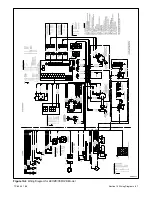
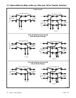
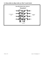
Страница 89: ...TP 6255 7 06 89 Section 10 Wiring Diagrams ADV6845B F Figure 10 4 Wiring Diagram Schematic for All Models ...
Страница 92: ...TP 6255 7 06 92 Section 10 Wiring Diagrams Notes ...
Страница 100: ...TP 6255 7 06 100 ...
Страница 101: ...TP 6255 7 06 101 ...
Страница 102: ...TP 6255 7 06 102 ...
Страница 103: ...TP 6255 7 06 103 ...