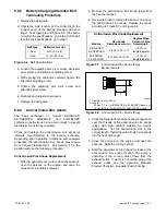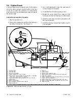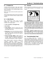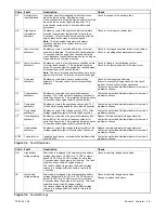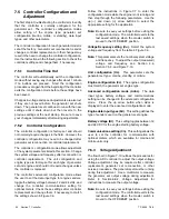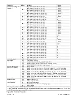
TP-6255 7/06
36
Section 5 Cooling System
8. Lubricate the gasket with silicon grease and attach
the gasket and coverplate to the seawater pump
housing.
9. Open the seacock.
10. Start the generator set and check for leaks.
11. Stop the generator set and repair leaks or replace
components as necessary.
5.8 Belt Tension
Rotating parts.
Can cause severe injury or death.
Operate the generator set only when
all guards, screens, and covers are in
place.
WARNING
Servicing the generator set when it is operating. Exposed
moving parts can cause severe injury or death.
Keep
hands, feet, hair, clothing, and test leads away from the belts
and pulleys when the generator set is running.
Replace
guards, screens, and covers before operating the generator
set.
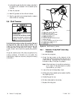
Check the belt tensions at the interval specified in the
service schedule. If tensions are not within the
specifications, adjust as necessary using the following
procedures.
1
11
10
9
8
7
6
5
2
3
4
TP-5586-3
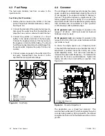
1. Engine-driven water pump pulley
2. Adjusting arm pivot screw
3. Battery charging alternator pulley
4. Alternator adjusting screw
5. Alternator pivot screw
6. Check the alternator belt tension here
7. Crankshaft pulley
8. Check the seawater pump belt tension here
9. Seawater pump adjusting screw
10. Seawater pump pulley
11. Pivot screw
Figure 5-5
Belt Tension (Typical)
5.8.1
Seawater Pump Belt Tensioning
Procedure
1. Remove the belt guard.
2. Check the belt tension at the midpoint of the
longest span of the belt using a belt-tensioning tool
set to 55 ft. lbs. See Figure 5-5. Recheck a new
belt tension after 10 minutes of operation.
Note:
If the belt tension is not within specifications,
go to step 3. If the belt tension is within
specifications, go to step 7.
3. Loosen the pivot and adjusting screws.
4. While prying the seawater pump outward, tighten
the adjusting screw.
5. Tighten the pivot screw.
6. Recheck and adjust as necessary.
7. Replace the belt guard.
Содержание 6.5-27EFOZD
Страница 1: ...Marine Generator Sets Models 8 32EOZD 6 5 27EFOZD TP 6255 7 06a Service ...
Страница 12: ...TP 6255 7 06 12 Service Assistance Notes ...
Страница 22: ...TP 6255 7 06 22 Section 1 Specifications Notes ...
Страница 28: ...TP 6255 7 06 28 Section 3 Intake and Exhaust System Notes ...
Страница 62: ...TP 6255 7 06 62 Section 7 Controller Notes ...
Страница 78: ...TP 6255 7 06 78 Section 8 Component Testing and Adjustment Notes ...
Страница 87: ...TP 6255 7 06 87 Section 10 Wiring Diagrams GM46351 Figure 10 2 Wiring Diagram for 9EOZD 7EFOZD Model ...
Страница 88: ...TP 6255 7 06 88 Section 10 Wiring Diagrams ADV6845A F Figure 10 3 Wiring Schematic for All Models ...
Страница 89: ...TP 6255 7 06 89 Section 10 Wiring Diagrams ADV6845B F Figure 10 4 Wiring Diagram Schematic for All Models ...
Страница 92: ...TP 6255 7 06 92 Section 10 Wiring Diagrams Notes ...
Страница 100: ...TP 6255 7 06 100 ...
Страница 101: ...TP 6255 7 06 101 ...
Страница 102: ...TP 6255 7 06 102 ...
Страница 103: ...TP 6255 7 06 103 ...


