


TP-6255 7/06
68
Section 8 Component Testing and Adjustment
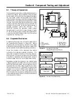
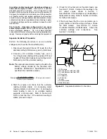
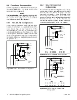
F+
F--
AC
AC
AC
TP-5983-7
1
2
5
4
6
7
8
3
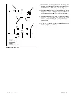
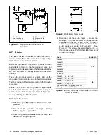
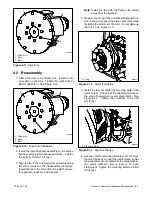
1. Main field (rotor)
2. Stator windings
3. Frame connection
4. Shaft connection
5. Rectifier module
6. Megohmmeter
7. Armature
8. Exciter field
Figure 8-10
Megohmmeter Connections on
Main Field
8.7 Stator
The stator consists of a series of coils of wire laid in a
laminated steel frame. The stator leads supply voltage
to the AC load and exciter regulator.
Before testing the stator, inspect it for heat discoloration
and visible damage to the housing lead wires and
exposed and varnished areas of the frame laminations.
Be sure the stator is securely fastened in the stator
housing.
The stator produces electrical output (AC) as the
magnetized main field rotates within the stator windings.
Test the condition of the stator according to the following
procedure.
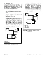
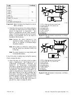
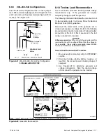
Leads 1, 2, 3, and 4 are the generator output leads.
Leads 55 and 66 are the voltage regulator supply and
sensing leads. Refer to the schematic in Figure 8-11
when performing the following tests.
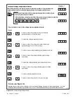
Stator Test Procedure:
1. Place the generator master switch in the OFF
position.
2. Disconnect the generator set engine starting
battery, negative (--) lead first.
3. Check the generator output lead connections. See
Section 10, Wiring Diagrams.
3
4
55
2
1
44
11
6196
66
Figure 8-11
Alternator Stator Leads
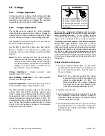
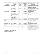
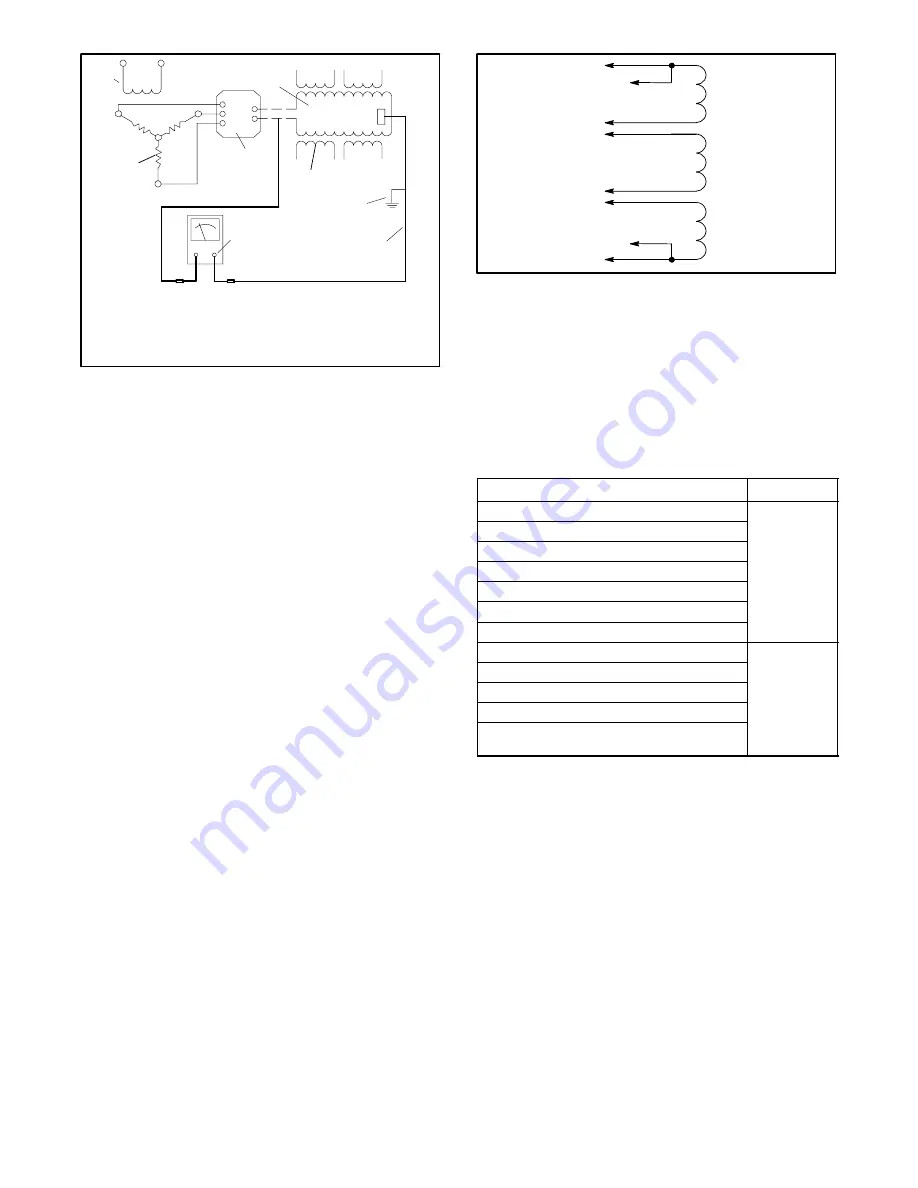
4. Disconnect all the stator leads to isolate the
windings. To check the stator continuity, set the
ohmmeter on the R x 1 scale. Check the stator
continuity by connecting the meter leads to the
stator leads as shown in Figure 8-11.
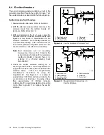
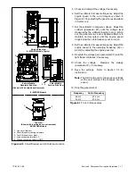
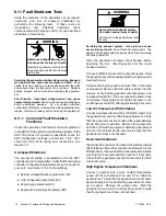
See
Figure 8-12 for single-phase and Figure 8-13 for
three-phase values. Perform the stator tests on all
the stator windings.
Leads
Continuity
1 and 2
1 and 11
2 and 11
3 and 4
Yes
3 and 44
4 and 44
55 and 66
1 and 3, 4, 44, 55, or 66
2 and 3, 4, 44, 55, or 66
3 and 1, 2, 11, 55, or 66
No
4 and 1, 2, 11, 55, or 66
No
Any stator lead and ground on stator
housing or frame laminations
Figure 8-12
Stator Continuity Test Results on a Good
Stator (1-Phase)
Содержание 6.5-27EFOZD
Страница 1: ...Marine Generator Sets Models 8 32EOZD 6 5 27EFOZD TP 6255 7 06a Service ...
Страница 12: ...TP 6255 7 06 12 Service Assistance Notes ...
Страница 22: ...TP 6255 7 06 22 Section 1 Specifications Notes ...
Страница 28: ...TP 6255 7 06 28 Section 3 Intake and Exhaust System Notes ...
Страница 62: ...TP 6255 7 06 62 Section 7 Controller Notes ...
Страница 78: ...TP 6255 7 06 78 Section 8 Component Testing and Adjustment Notes ...
Страница 87: ...TP 6255 7 06 87 Section 10 Wiring Diagrams GM46351 Figure 10 2 Wiring Diagram for 9EOZD 7EFOZD Model ...
Страница 88: ...TP 6255 7 06 88 Section 10 Wiring Diagrams ADV6845A F Figure 10 3 Wiring Schematic for All Models ...
Страница 89: ...TP 6255 7 06 89 Section 10 Wiring Diagrams ADV6845B F Figure 10 4 Wiring Diagram Schematic for All Models ...
Страница 92: ...TP 6255 7 06 92 Section 10 Wiring Diagrams Notes ...
Страница 100: ...TP 6255 7 06 100 ...
Страница 101: ...TP 6255 7 06 101 ...
Страница 102: ...TP 6255 7 06 102 ...
Страница 103: ...TP 6255 7 06 103 ...