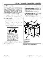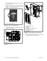
TP-6255 7/06
75
Section 8 Component Testing and Adjustment
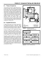
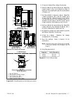
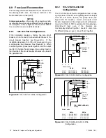
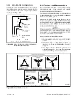
8.11.2 Fault Shutdown Switches
Check the low oil pressure and high engine temperature
shutdown switches on the engine by performing the
following tests.
If the sensor does not function as
described, replace it.
Hazardous voltage.
Can cause severe injury or death.
Operate the generator set only when
all guards and electrical enclosures
are in place.
Moving rotor.
WARNING
Servicing the generator set when it is operating. Exposed
moving parts can cause severe injury or death.
Keep
hands, feet, hair, clothing, and test leads away from the belts
and pulleys when the generator set is running.
Replace
guards, screens, and covers before operating the generator
set.
Short circuits.
Hazardous voltage/current can cause
severe injury or death.
Short circuits can cause bodily injury
and/or equipment damage
.
Do not contact electrical
connections with tools or jewelry while making adjustments or
repairs. Remove all jewelry before servicing the equipment.
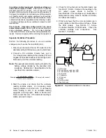
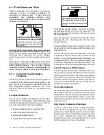
Temperature Sensor (CTS)
The coolant temperature sensor (CTS) is used to
monitor engine temperature for the high engine
temperature fault shutdown (HE). See Figure 8-23 for
the coolant temperature sensor location.
Set the
generator set master switch to the OFF position and
allow the generator set to cool. Disconnect the CTS and
use an ohmmeter to measure the resistance across the
sensor. The sensor resistance varies with temperature
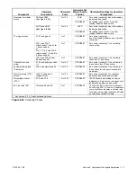
and should be within the values shown in Figure 8-24. If
the resistance is very low (indicated a short circuit) or
very high (indicating an open circuit) replace the CTS.
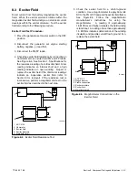
Low Oil Pressure (LOP) Switch
See Figure 8-25 for the low oil pressure (LOP) switch
location.
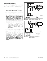
Remove the LOP switch and install an oil pressure
gauge to verify that the engine oil pressure is within the
range specified in Figure 8-26 before testing or
replacing the LOP switch.
To test the LOP switch,
reinstall the switch and start the generator set. If the unit
shuts down, disconnect lead 13 from the LOP switch
and reset the controller. Restart the generator set and
verify that it does not shut down. A successful restart
indicates a bad LOP switch. Replace the switch.
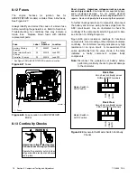
1
1. Coolant Temperature Sensor
Figure 8-23
Coolant Temperature Sensor Location
(8EOZD Model Shown)
Temperature,
_
C (
_
F)
Resistance, Ohms
30
(86)
2106--2392
100 (212)
182--198
Figure 8-24
Coolant Temperature Sensor Resistance
Readings
1
1. Oil pressure switch
Figure 8-25
Oil Pressure Switch Location
(24EOZD Model Shown)
Model
Oil Pressure Range
MPa (kg/cm
2
)
8--32EOZD and 6 5--27EFOZD
0 29 0 39 (3 4)
8--32EOZD and 6.5--27EFOZD
0.29--0.39 (3--4)
Figure 8-26
Oil Pressure Range
Содержание 6.5-27EFOZD
Страница 1: ...Marine Generator Sets Models 8 32EOZD 6 5 27EFOZD TP 6255 7 06a Service ...
Страница 12: ...TP 6255 7 06 12 Service Assistance Notes ...
Страница 22: ...TP 6255 7 06 22 Section 1 Specifications Notes ...
Страница 28: ...TP 6255 7 06 28 Section 3 Intake and Exhaust System Notes ...
Страница 62: ...TP 6255 7 06 62 Section 7 Controller Notes ...
Страница 78: ...TP 6255 7 06 78 Section 8 Component Testing and Adjustment Notes ...
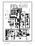
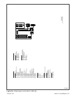
Страница 87: ...TP 6255 7 06 87 Section 10 Wiring Diagrams GM46351 Figure 10 2 Wiring Diagram for 9EOZD 7EFOZD Model ...
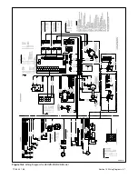
Страница 88: ...TP 6255 7 06 88 Section 10 Wiring Diagrams ADV6845A F Figure 10 3 Wiring Schematic for All Models ...
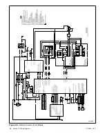
Страница 89: ...TP 6255 7 06 89 Section 10 Wiring Diagrams ADV6845B F Figure 10 4 Wiring Diagram Schematic for All Models ...
Страница 92: ...TP 6255 7 06 92 Section 10 Wiring Diagrams Notes ...
Страница 100: ...TP 6255 7 06 100 ...
Страница 101: ...TP 6255 7 06 101 ...
Страница 102: ...TP 6255 7 06 102 ...
Страница 103: ...TP 6255 7 06 103 ...


